52 Power Mower 5400 Edition 02.97
5. Maintenance
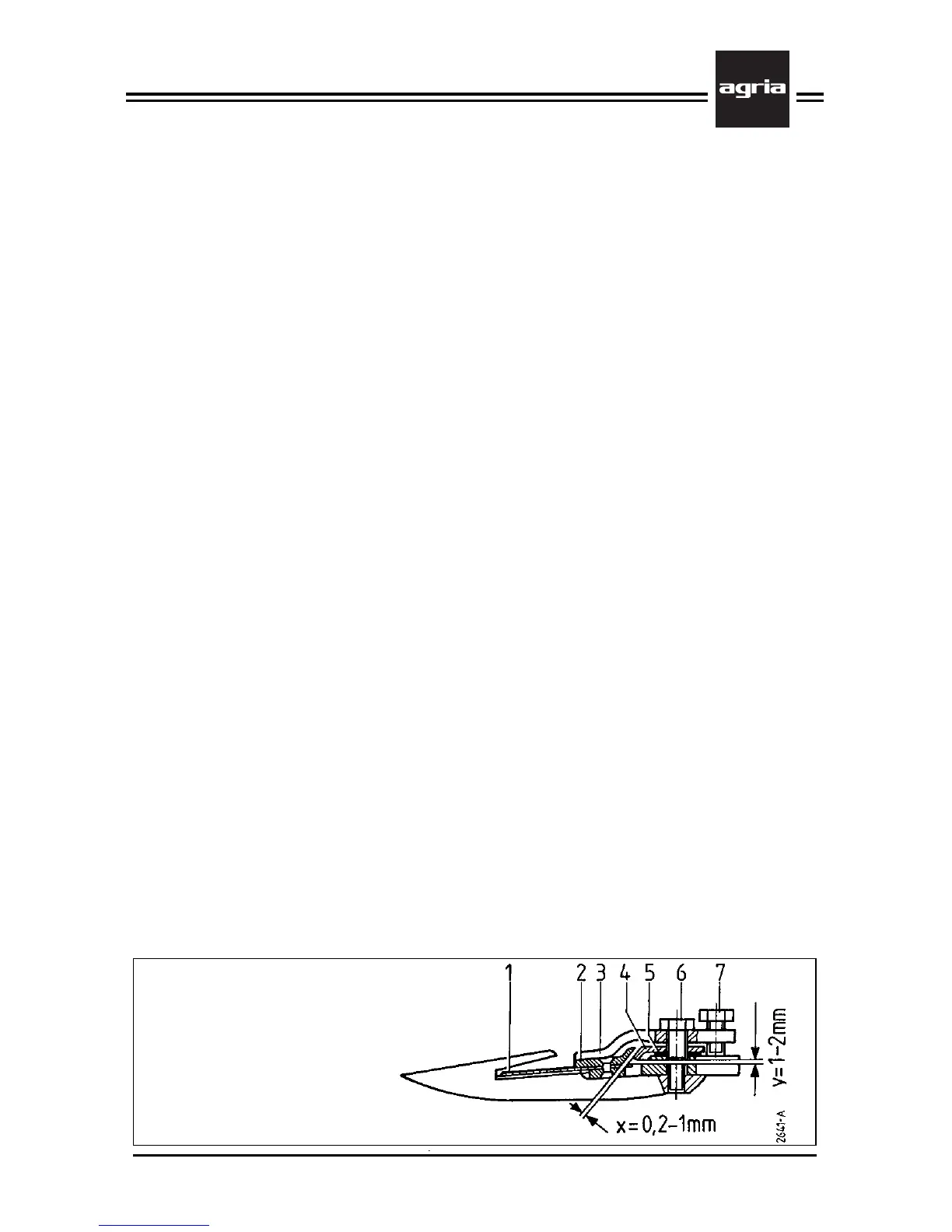
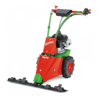
Finger Cutter Bar
1 Mowing knife
2 Guide bar
3 Knife holder
4 Friction plate
5 Distance plate
6 Set screw
7 Set screw
Finger Cutter Bar
W
Stop the engine, remove
spark plug connector and
wear safety gloves.
Knife Removal
l
On the rocker arm mower: Loosen
the clamping screw (K/5, page 28).
l
Remove the knife driver
l
Pull the knife out to the side - use a
suitable tool such as a wooden stick
l
Clean the cutter bar and oil it with
Bio lubrication oil
W
Always attach the knife guard
before you lay the mowing
knife aside.
Knife Attachment
l
To attach the knife reverse the above
order
l
On the rocker arm mower:
As a first step, loosen the clamping
screw (K/5, page 28) which holds the
link pin and tighten it after the attach-
ment (100 Nm)
l
Check whether it is necessary to ad-
just the knife guiding devices and ad-
just them if necessary
Correct Adjustment
l
There is no play between the guide
bar (2) and the knife holder (3). The
guide bar touches 1/3 of the knife hold-
er’s front end.
l
The chamfered gliding faces of the
friction plate (4) and the guide bar (2)
are parallel to each other and have a
play (x) of 0.2mm to 1mm.
l
The distance (Y) between the blades
(1) sticking out to the rear and the fric-
tion plate (4) is 1mm to 2mm.
l
The knife is easy to move sideways
by hand.
Setting the knife guiding
devices
In the course of operation cutting qual-
ity declines as a result of uneven wear
on the knife guiding parts. Readjustment
of these parts will restore the cutting
quality.
l
Remove a play between knife holder
(3) and guide bar (2) by turning the set
screw (7).
l
To remove excessive play (x), loosen
the 2 attachment bolts (6) to move the
friction plate (4) to the desired position.
Then retighten both attachment bolts
(6).
l
These adjustments may lead to ex-
cessive play between the knife holder
(3) and guide bar (2). Remove this by
turning the set screw (7).
l
To correct the distance (Y), add or
remove a number of distance plates (5).
This becomes only necessary, if too
many or too few distance plates (5) were
placed under the friction plate (4) when
the cutter bar was assembled.