Edition 02.97 Power Mower 5400 53
5. Maintenance
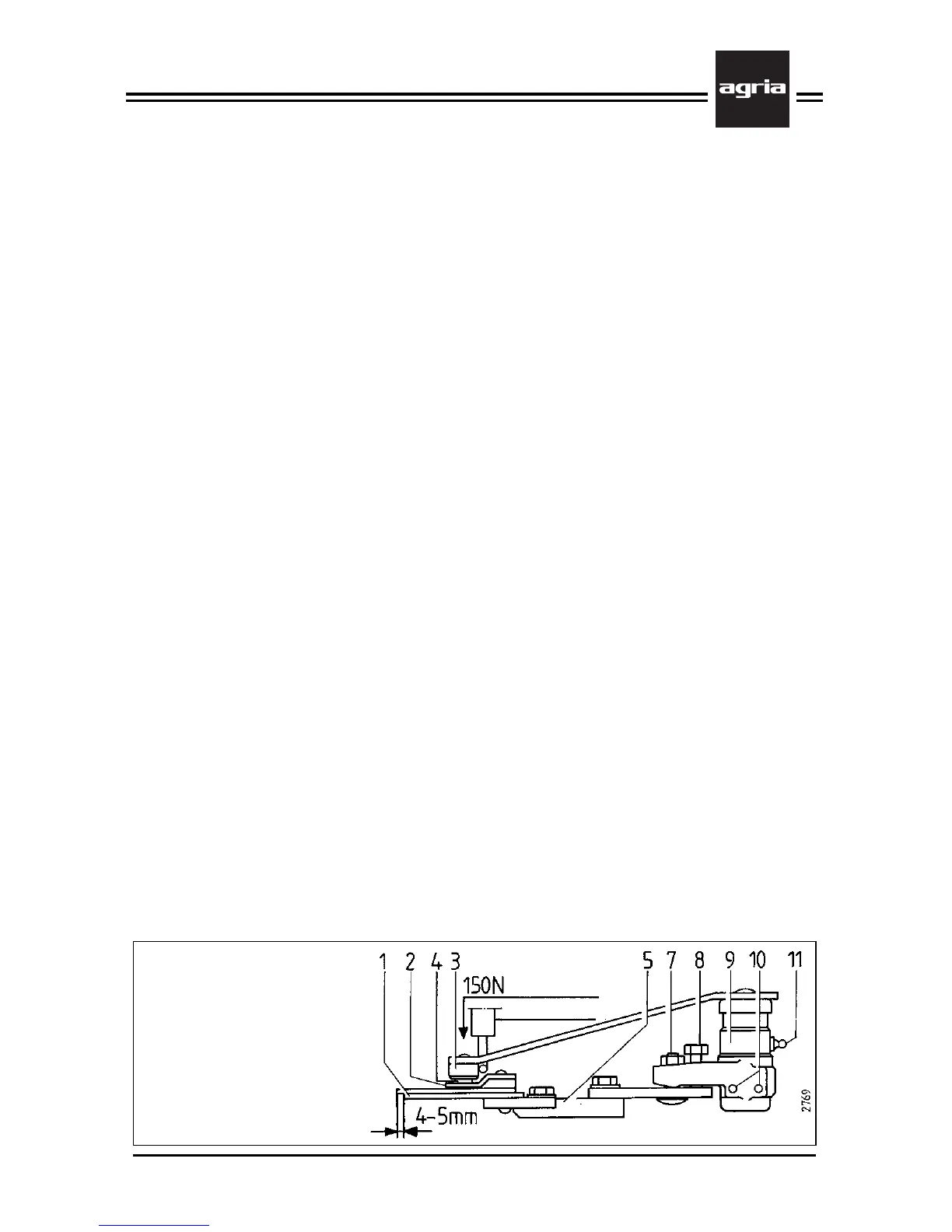
1 Cutter bar blade
2 Pin rest
3 Pin sleeve
4 Driver pin
5 Cutter bar back
7 Attachment bolt
8 Set screw
9 Bearing part
10 Clamping sleeve
11 Lubrication nipple
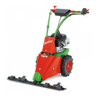
Municipal Cutter Bar
Pressure
Spring balance
Municipal Cutter Bar
W
Stop the engine, remove
spark plug connector and
wear safety gloves.
Knife Removal
l
Lift the pivot arm with the lever which
is supplied with the cutter bar off the
driver pin (4) and pivot it to the side and
away from the knife
l
Pull the knife out to the front
l
Clean the cutter bar and oil it with
Bio-lubrication oil
W
Always attach the knife guard
before you lay the mowing
knife aside.
Knife Attachment
l
To attach the knife reverse the above
order
l
On the rocker arm mower:
As a first step, loosen the clamping
screw (C/5) which holds the link pin and
retighten it after the attachment
(100 Nm, see page 28)
Maintenance
l
Lubricate the nipple (11) with Bio-lu-
brication grease after each operation
and after washing the mower, but after
8 operating hours as a minimum.
l
Additionally, lubricate new pivot arm
guides once after approx. 1 operating hour
l
Apply some Bio-lubrication grease to
the driver pins (4) on the knife each time
you have replaced the knife and after
8 operating hours.
Adjustment of Knife Guiding Devices
l
At intervals of 25 operating hours
check the pressure of the pivot arms
(approx. 150 N), using a conventional
spring balance
l
To increase or adjust the pressure of
the pivot arms:
– Loosen the 2 attachment bolts (7) on
the bearing parts
– Adjust the pressure to approx. 150 N
by turning the set screws (8). Then reat-
tach the 2 adjustment bolts (7).
– Each time you have loosened the bolts
(7) ensure that the bearing part (9) is at
right angles to the cutter bar (5).
– Ensure also that the tips of the knife
blades protrude 4mm to 5mm from the
blades of the cutter bar in middle posi-
tion.
l
Replace the driver pin (4) or its sleeve
(3), if the play between these two parts
is greater than 2mm or if the sleeve (3)
touches the pin rest (2).
l
When fitting new clamping sleeves
(10) ensure that the slots point out-
wards.