Remote-controlled All-electric Tool Carrier agria 9700e
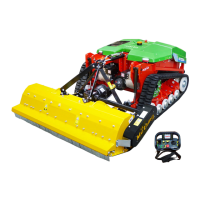
The drift (B/14) assists you in driving a straight contour line on
a slope. The longer you drive a contour line across the slope,
the more the machine tends to drive downhill, especially when
it is pushing a heavy mounted implement. With the drift, you
can countersteer this movement and drive in a straight line
across the slope. Turn the rotary switch to the right to prevent
the machine from sagging downhill to the left. Turn the rotary
switch to the left if you do not want the machine to sag downhill
to the right. The drift is changed automatically when the driving
direction changes; you can continue to operate the machine as
usual.
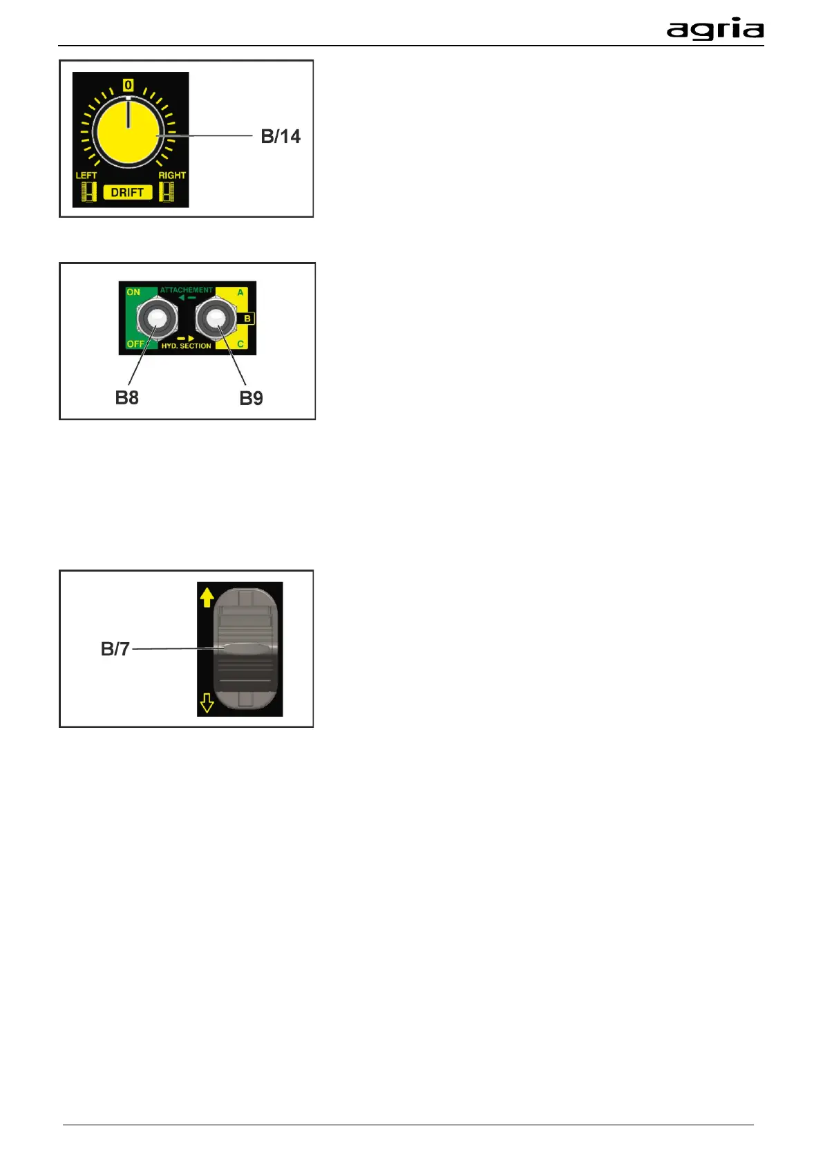
Three-point mounting bracket:
You switch on the PTO shaft with the selector switch (B/8).
The selector lever (B/9) is used to select the hydraulic control
circuit.
Use the analogue lever for moving (B/7) as described in the
following section.
The hydraulic control circuits are:
• A: With hydraulic control circuit A you can retract and ex-
tend the upper links.
• B: With the hydraulic control circuit B you can adjust the
height of the lower links.
• (Optional) C: With the hydraulic control circuit C you can
operate the hydraulic additional function of your mounted
implement, for example a lateral adjustment. Do not con-
nect a hydraulic motor to hydraulic control circuit C.
With the analogue lever, you can operate the function of the
selected hydraulic control circuit.
The speed of adjustment depends on the deflection of the an-
alogue lever
4.5.1 Recommended operation mode:
Floating position
You can use the ‘floating position’ function to operate mounted implements on uneven soils. The floating
position compensates the unevenness and guarantees a neat work result.
Before activating the floating position, lift the mounted implement to the maximum height of your desired
working area.
Use the FLOAT (B21) key to activate the floating position. Activating the floating position limits the upward
movement of the mounted implement up to the point at which you have activated the floating position
(B21). Ensure adequate travel or activate the floating position at the highest point of lifting.
Lift the mounted implement at the end of the row if you turn the machine after you have processed a row
with the mounted implement in floating position. Turn the machine. Activate the floating position (B21) and
the mounted implement will sink to ground level.
When the floating position is activated it may take a moment until the hydraulic system reacts to a com-
mand given via the analogue lever (B/7).