Chapter 5: Changing Capture Hoods 45
Alternate Hood Installation
Refer to Figures 17 through 20 to determine the frame channels needed to assemble any of the standard
sized frames. Select the pieces required for the frame size desired and assemble with the aid of the
appropriate figure. Each channel is labeled with its number for easy identification. Several sections
(numbers 1, 3, and 4) consist of a straight channel portion (each a different length) and a corner piece.
This corner piece has an eyelet and slot arrangement which mates with a similar eyelet and slot at the
end of the straight portion of the channel pieces (see Figure 17). These pieces can be slid together and
are self-locking by means of a retention spring. The arrangement forms a rugged frame which is
additionally strengthened when the hood is attached.
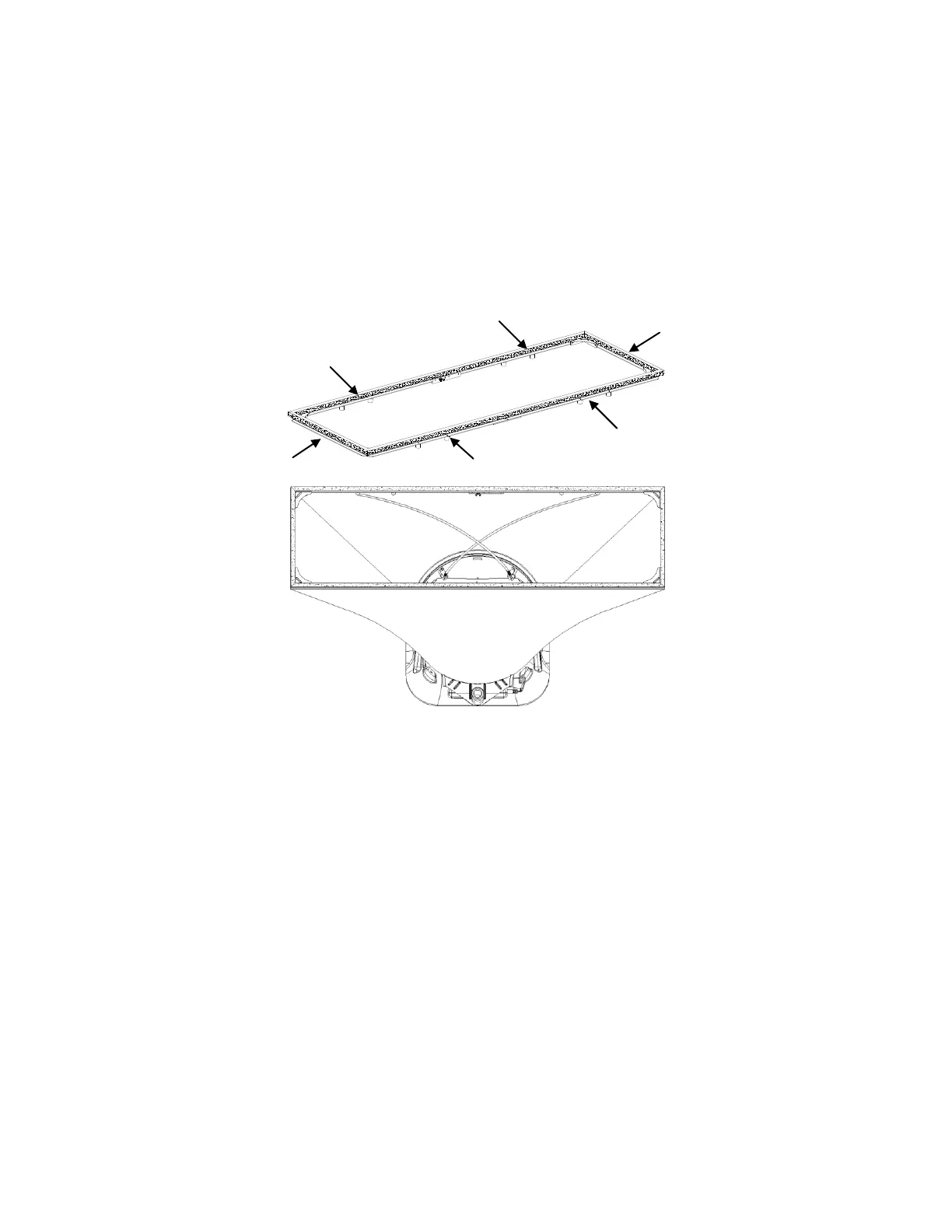
Figure 17: 1 ft 4 ft (305 mm 1220 mm) hood and frame. The support poles always cross as pairs at the
front and back of the fabric hood. For the 1 ft 4 ft (305 mm 1220 mm), the support poles are inserted into
the outside ferrule locations.