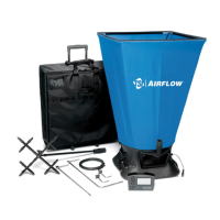
Chapter 5: Changing Capture Hoods 49
Figure 22: Frame Side Coupler Assembly
Each hood is constructed in a trapezoidal shape, sewn together so that one open end forms a round
attachment to the base, and the other forms a square or rectangle large enough to fit its matching frame
assembly. Around the frame end of the hood, an elastic shock cord has been sewn into the hood. This
cord is of a size such that it can be pushed into the open side of the U-shaped channels of the frame.
In general, attach a hood to the frame first, and then to the base unit. By stretching around the frame
corners the cord is slightly reduced in diameter and is easier to press into the frame channel.
Note
The hood corners should always be aligned with the corners of the base, near the hood support
brackets. The base has rivets located in the corners which can be used as a guide for aligning
the hood corners.
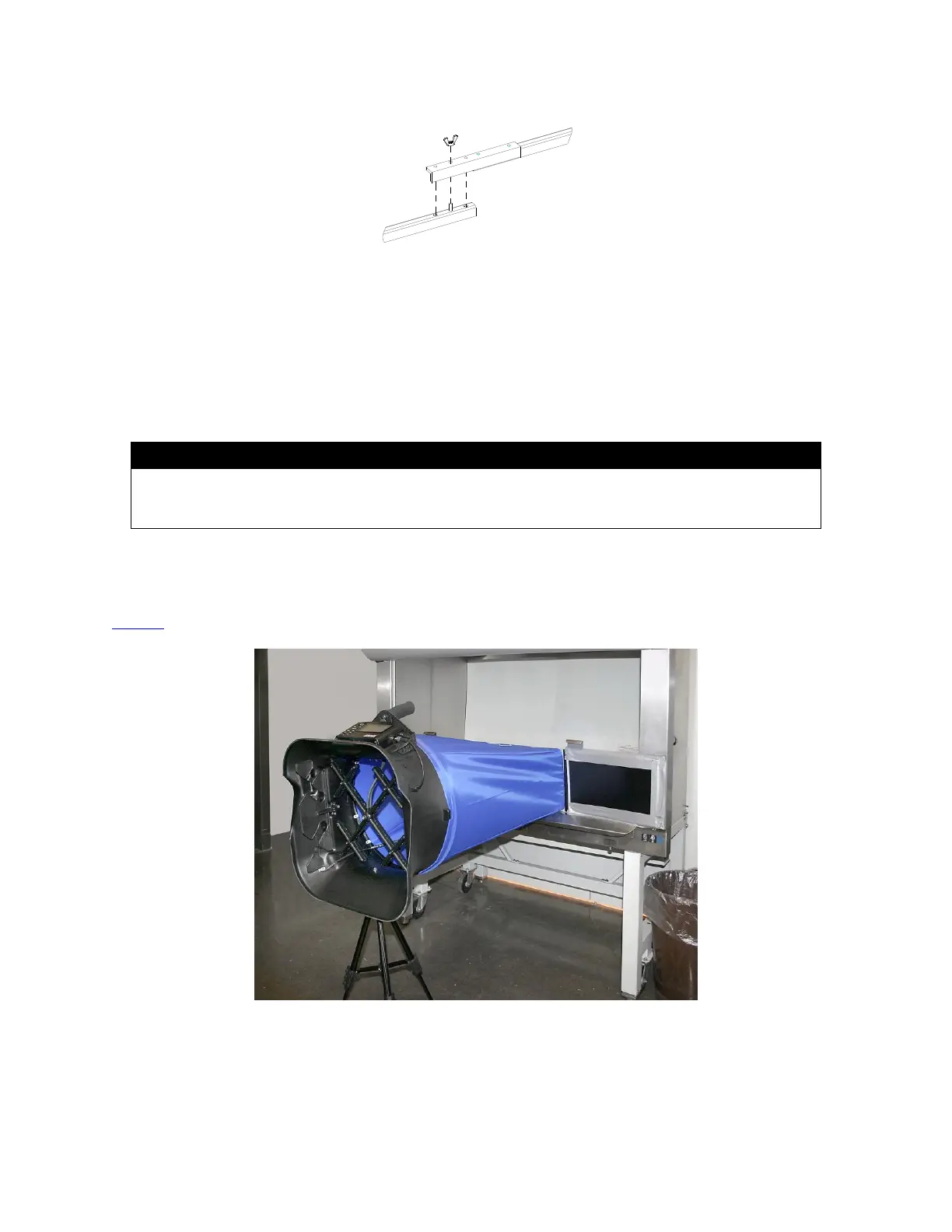
Direct Inflow Measurement Hood for Biological Safety Cabinets
The BSC hood kits for the models PH731 are designed to measure the inflow or exhaust flow through a
biological safety cabinet (see Figure 23). Part numbers and description of each kit can be found in
Table 2 of this manual.
Figure 23: Direct Inflow Measurement Hood
 Loading...