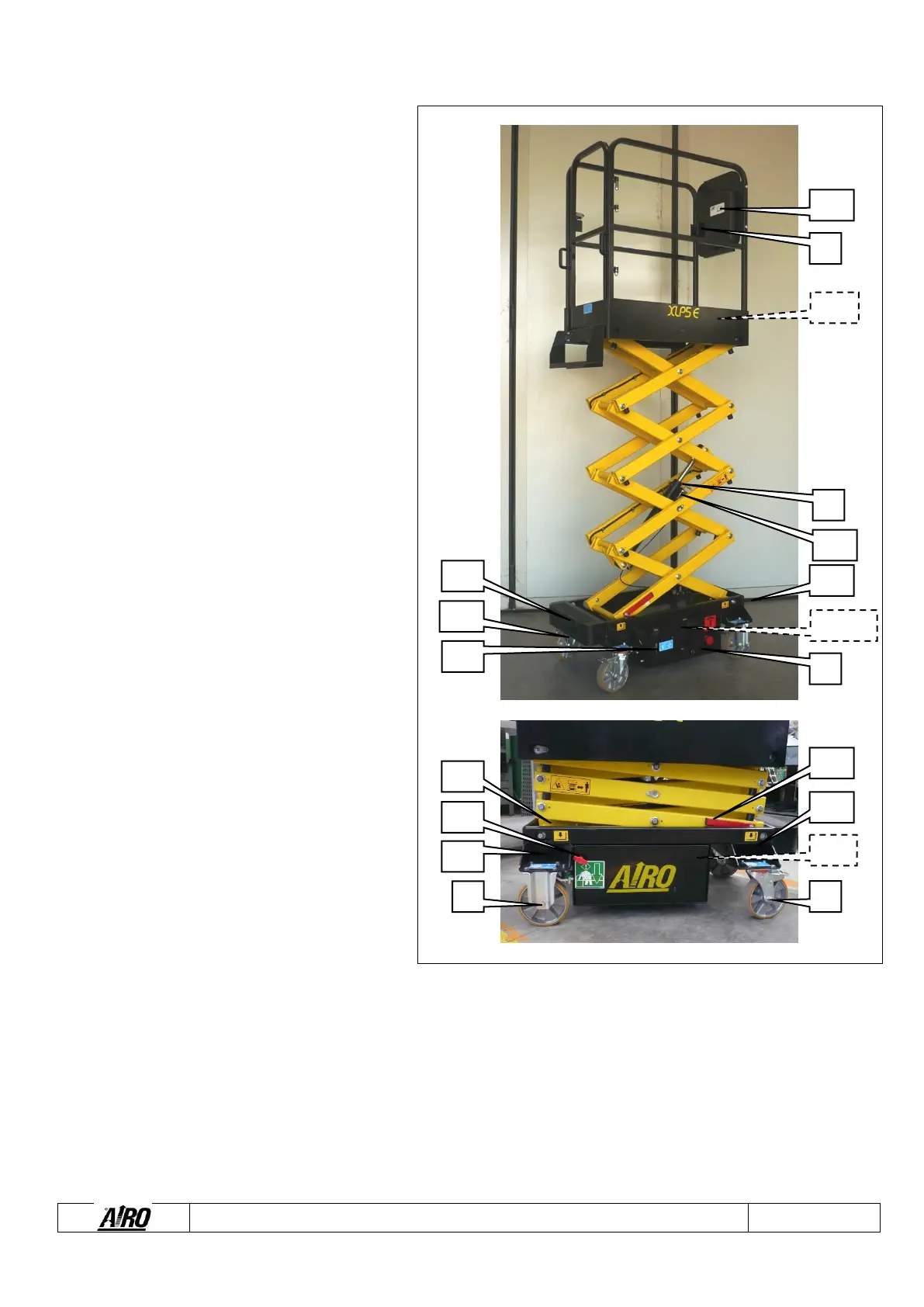
Alongside is a diagram showing the machine and its
components.
1) Platform control push-button panel
2) Box components
3) Control panel
4) Hydraulic control unit
5) Steering wheels with pedal parking brake
6) Fixed wheels with automatic parking brakes
7) 230V plug (optional)
8) Spirit level for visual check of machine levelling
(optional)
9) Lifting cylinders
10) Lowering control valves
11) Battery
12) Battery charger
13) Inclinometer
14) Manual device for emergency lowering
15) Platform height control M1 microswitch
16) Stopping levers of the lifting structure
17) Document box
18) Battery charger power cable location
19) Wheel chocks for forklift truck
20) Transport fixing holes.