Chapter 2: Installation
Controller Box Installation
Page 23
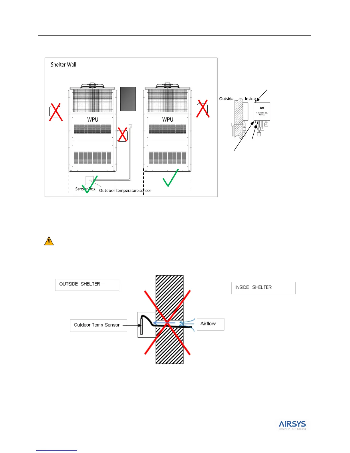
Figure 16 illustrates the relationship of the sensor to the installed WPUs
Figure 16: Location of Outdoor Temperature Sensor
Note: punching out the holes on the sides and the bottom of the sensor box is critical to allow proper airflow and to
facilitate drainage from rain and dew.
Important. Ensure no air leakage exists from inside the shelter to the box housing the outdoor temperature
sensor. Any path whereby air could exit the shelter and arrive in the sensor box will adversely affect the outdoor
temperature sensor reading. The hole in the shelter wall where the outdoor temperature sensor has passed through
must be 100% sealed so no air can leak out of the shelter.
Figure 17: Ensure No Leakage
Controller Box
(Inside Shelter)
Indoor Temp Sensor
Backup Indoor
Temperature Sensor