MPC2500 Operator’s Manual rev 1.0
95
Applying filters to an
incoming signal
You can apply the internal filters to the incoming signal from
REC IN (Analog) or DIGITAL IN (Digital). You can also
control the cut-off frequency and Resonance in real-time by
using Q-Link slider/knob.
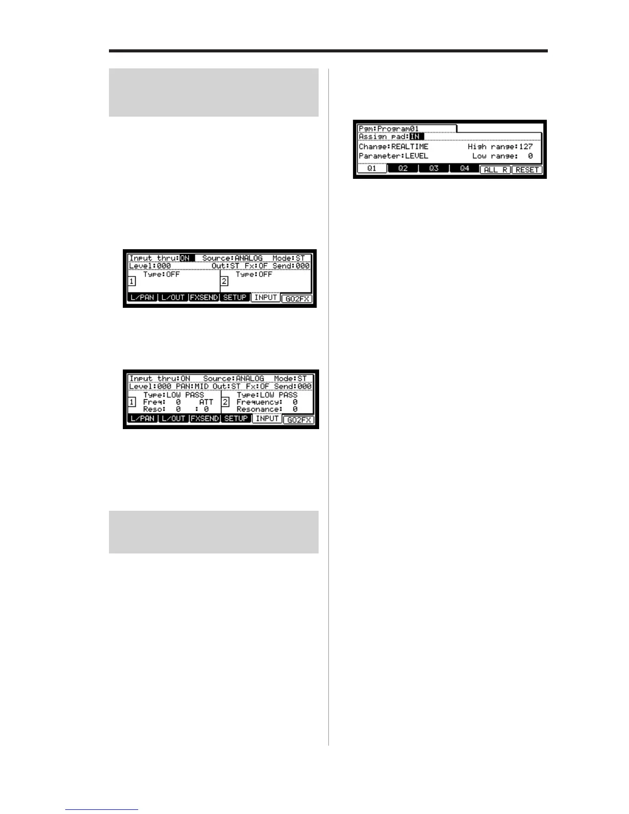
01. Press [INPUT THRU] key.
The INPUT page will be displayed.
You can also get to the INPUT page by pressing the
[F5] (INPUT) key in the MIXER mode.
Set the necessary parameter in each field while refer-
ring to the Applying effects to an incoming signal.
02. In the Type field, select the filter type.
Setting set the filter type is same as in the Filter page
while in PROGRAM mode. Refer to “Editing the
sound of a sample” in the PROGRAM mode.
Note : You cannot use the Filter Modulation with INPUT THRU.
Using Q-Link feature in
INPUT THRU mode
You can control the input level, pan, and the filter’s param-
eter ( Cut-off frequency and Resonance) in real-time by us-
ing Q-Link slider/ knob.
Note : You cannot record the real-time control of the INPUT
THRU into the sequence.
Note : In this explanation, the necessary setting on the filter and
the input level/pan for INPUT THRU mode should be entered
first. If you haven’t set any parameter for them, set them while
referring to “Applying effects to an incoming signal” and “Ap-
plying filters to an incoming signal”
01. Select SLIDER mode by pressing [MODE] key then
hitting PAD 1 (SLIDER)
02. In the Assign pad field, select IN.
Note : Only “REALTIME” will be available in the Change field.
03. In the Parameter field, adjust the desired parameter.
LEVEL : This control the input signal volume level.
CUTOFF1+2 :
This controls the cutoff frequency of both Fil-
ter 1 and Filter 2.
CUTOFF1 : This controls the cutoff frequency of Filter 1.
CUTOFF2 : This controls the cutoff frequency of Filter 2.
RESO1+2 : This controls the resonance value of both Fil-
ter 1 and Filter 2.
RESO1 : This controls the resonance value of Filter 1.
RESO2 : This controls the resonance value of Filter 2.
PAN : This control the sample’s pan position.
04. In the High range field and Low range field, set the
upper and lower limit of the slider or knobs.
The value of the controlled parameter is deter-
mined by the value set here. The value depends
on the type of the parameter selected in the Pa-
rameter field.
LEVEL : 0 –100.
This is linked to the value in Level field in the INPUT
page. If you change the slider or knob, the value will
be changed depending on the value in INPUT page.
CUTOFF1+2 / CUTOFF1 / CUTOFF 2
: -50 - +50
This value also offsets the current setting in the
INPUT page.
RESO1+2 / RESO1 / RESO2 : -50 - +50
Again, this value offsets the current setting in the
INPUT page.
Note : In the Input THRU mode, you cannot record the moving
of Q-Link in the sequence.
 Loading...