─ Maximum conductor cross-section is 0.75 mm²
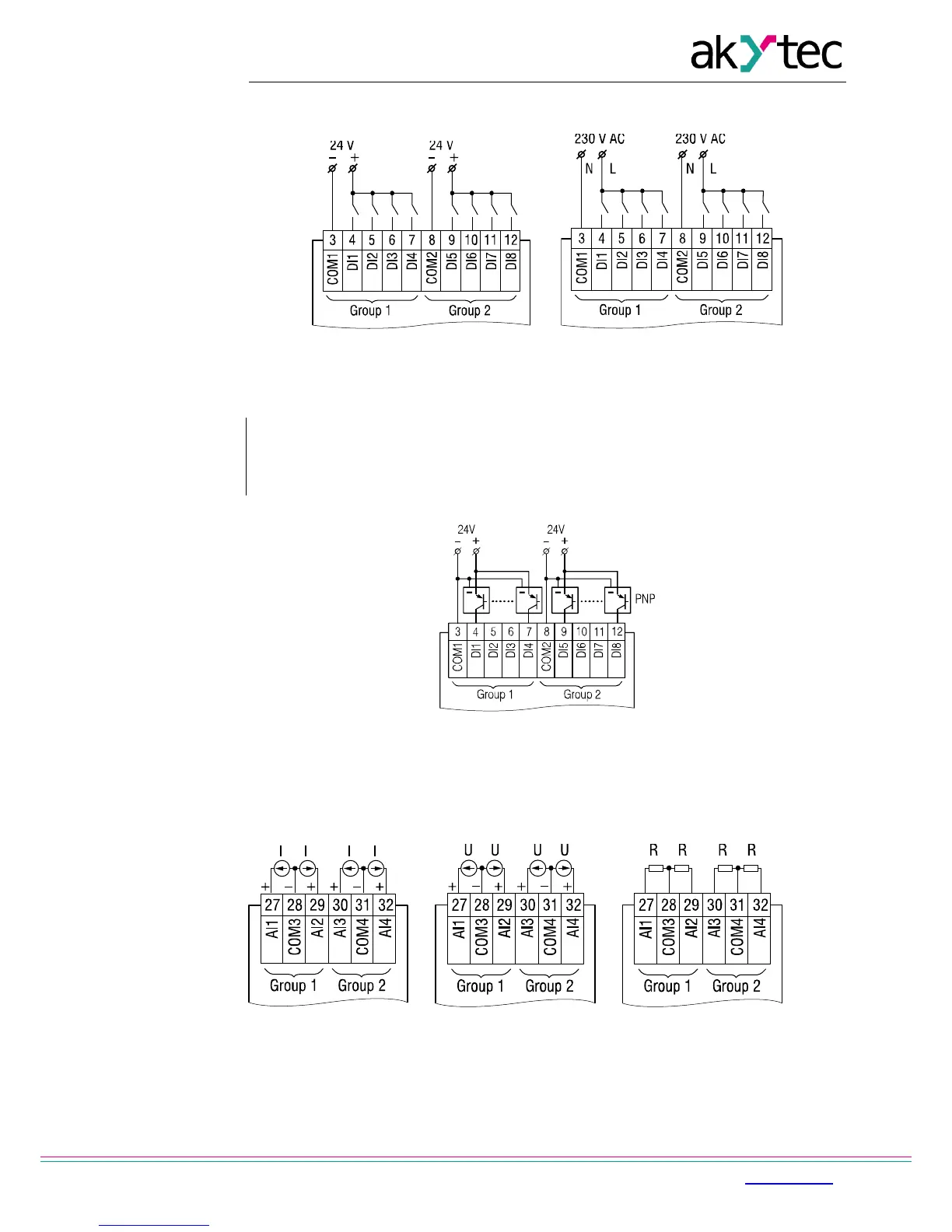
7.2.1 Inputs
a b
Fig. 7.2 Connecting switch contacts to digital inputs: a) PR200-24, b) PR200-230
Fig. 7.3 Connecting 3-wire sensors with PNP transistor outputs (PR200-230 only)
For PR200-24 it is allowed to connect sensors with switch contact and transistor outputs
within the same group. One voltage source can be used for two input groups.
The integrated voltage source 24 V can be used for all inputs.
a b c
7.4 Wiring of analog inputs: a) 4-20 mA, b) 0-10 V, c) 0-4000 ohm
Different sensors can be connected within a group (AI1/AI2 or AI3/AI4). For example, AI1
can be configured as a digital input and AI2 as an analog input 4-20 mA.