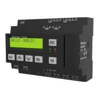
7.2.2 Outputs
Fig.7.5 Relay outputs
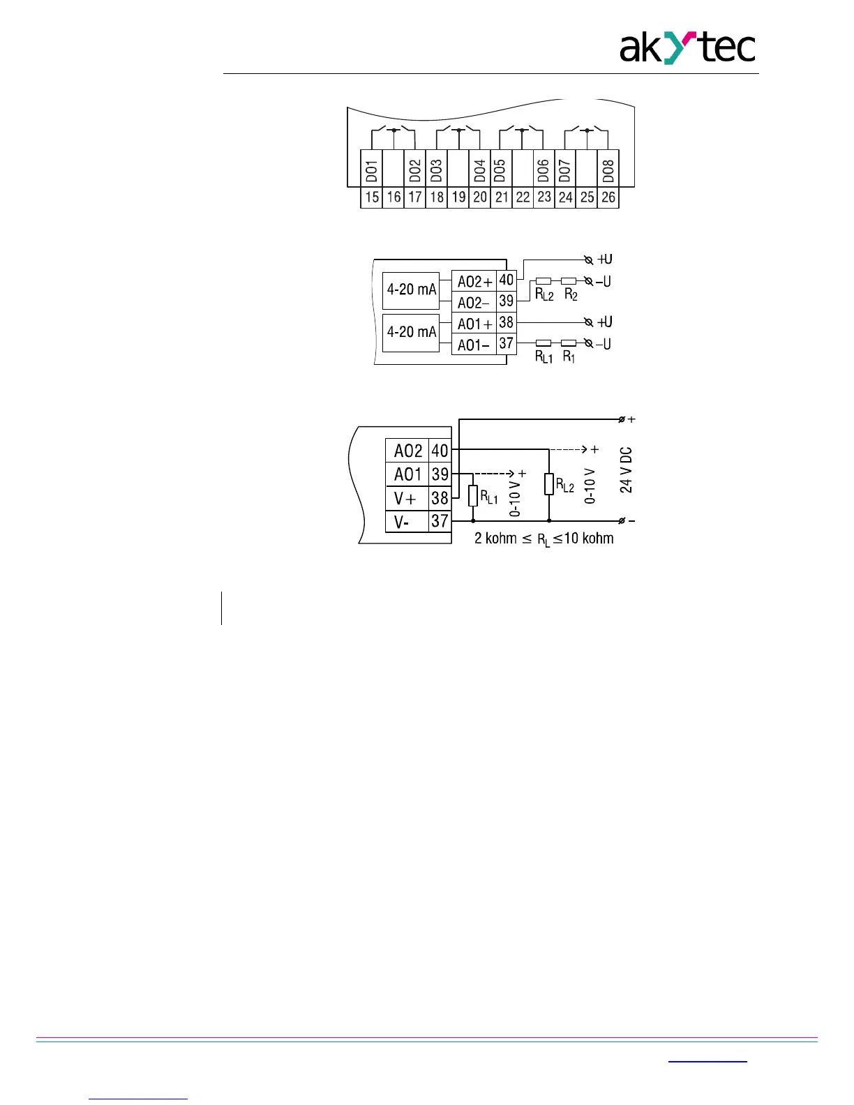
Fig. 7.6 Wiring of analog outputs 4-20 mA (PR200-X.2)
Fig. 7.7 Wiring of analog outputs 0-10 V (PR200-X.4)
NOTICE
The voltage of an external voltage source may not exceed 30 V.
The integrated voltage source can be used for analog output 4-20 mA or 0-10 V.
An external load resistor R
L
is required. The value of resistance R
L
depends on supply
voltage and can be determined from the diagram in Fig. 7.8. If a measuring resistance R
M
is
used for current measurement and R
M
< R
L
, then an additional load resistance R shall be
used for current limitation. Resistance R can be determined as follows:
R =
R
L
- R
M
Example 1
U = 12 V, R
L
= R
M
= 100 ohm
Example 2
U = 24 V, R
L
= 700 ohm, R
M
= 100 ohm, R = 600 ohm
The used resistance may differ from the calculated value by no more than ±10%.
The external voltage for the output 0-10 V may not exceed the range of 15…30 V.
The load resistance RL may not exceed the range of 2…10 kohm.
This type of output can be also powered from integrated voltage source 24V.