Mounting the Switch Chassis and Power Supplies
page 3-14 OmniSwitch 6465 Hardware Users Guide December 2019
Mounting the Switch
General Mounting Recommendations
Elevated Operating Ambient Temperature. If installed in a closed or multi-rack assembly, the operating
ambient temperature of the environment may be greater than the room’s ambient temperature. Therefore,
consideration should be given to the maximum rated ambient temperature (Tmra) listed in the
“OmniSwitch 6465 Chassis Details” section.
Reduced Air Flow. Installation of the equipment should be such that the amount of air flow required for
safe operation of the equipment is not compromised. Refer to “Airflow / Clearance Recommendations” on
page 3-14 for more information.
Mechanical Loading. Mounting of the equipment should be such that a hazardous condition is not
achieved due to uneven loading.
Circuit Overloading. Consideration should be give to the connection of the equipment to the supply
circuit and the effect that overloading of circuits could have on overcurrent protection and supply wiring.
Reliable Earthing. Reliable earthing of equipment should be maintained. Particular attention should be
given to supply connections other than direct connections to the branch (e.g., use of power strips).
Airflow / Clearance Recommendations
To ensure proper airflow, be sure that your switch is placed in a clean, well-ventilated area free of dust and
debris and provide minimum recommended clearance as shown below. Restricted airflow can cause your
switch to overheat, which can lead to switch failure. Refer to the following important guidelines:
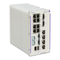
DIN Rail Mounting
The OmniSwitch chassis are DIN rail mountable. Refer to the following:
Minimum Recommended Clearances - P6 / P12 Models
To p ( D I N R a i l M o un t )
N/A - (If no equipment is installed above chassis)
1 inch - (If equipment is installed above chassis).
Bottom (DIN Rail Mount)
N/A - (If no equipment is installed below chassis)
1 inch - (If equipment is installed below chassis).
Sides (DIN Rail Mount) 2 inches
Front / Rear N/A
Minimum Recommended Clearances - P28 Model
Top 1.75 inch (1RU)
DNV Installations 1.75 inches (1 RU) for OS6465-P28 that requires a DNV power supply
cover, operating between -40°C to 55°C (-40°F to 131°F).
Bottom 1.75 inch (1RU)
Sides (DIN Rail Mount) 2 inches
Front / Rear N/A
 Loading...


