8 | Alderon Industries™ - Leading Edge Control Products
Mini Power Post™ Monitoring System - USER GUIDE
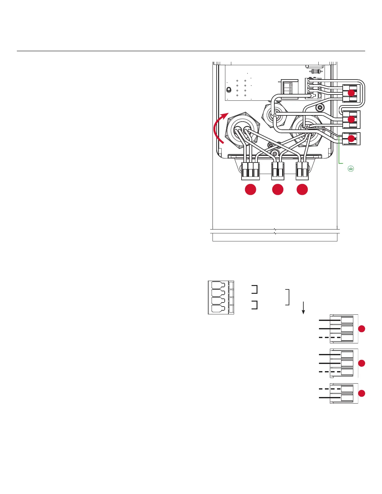
Wiring (continued)
STEP 1: WIRING
The wiring diagram shows four terminals on the quick snap
terminal block that consists of two pairs of connections. Make
sure to read and review the connector examples on page 7 for
proper installation prior to wiring.
Note: The quick snap terminal block, is herein referred to as
“terminal” for instruction purposes. The installation example
shown is for 120VAC, for 240VAC installation the neutral (N)
wire would be replaced by line connection (L2) and white wire
would include a red band to indicate the wire is hot.
1) The alarm and pump power connections are factory wired
from the terminals and pre-installed female receptacle in
the middle cable grip. The wires are terminated by the
pre-installed Wago connectors which are separated into
line, neutral, and ground connections.
2) The rst cable grip, starting at the right, has a cable grip
divider allowing for two cable sources to be brought into
the enclosure. The top side of the cable grip is used for
the both the alarm and pump power, attached in series.
The line (L1), neutral (N), and ground (G) wires each get
terminated by the Wago connectors. After bringing in the
cables, rmly tighten the cable grip by twisting clockwise
until securely fastened.
If the system is equipped with a remote alarm panel, high level
alarm oat switch, and/or lter switch, continue with the steps
below before proceeding to power connection or testing.
3) The rst cable grip, starting at the right, has a cable grip
divider allowing for two cable sources to be brought into
the enclosure. The bottom side of the cable grip is used
for the customer supplied sensor wire. Use the provided
Wago connectors to terminate the black (1C), red (1B),
and white (1A) wires. After bringing in the cables, rmly
tighten the cable grip by twisting clockwise until securely
fastened.
4) The third cable grip, on the left, has a cable grip divider
for the sensor wires. The high level alarm oat switch
black and white wires are paired with the black and
common sensor wires (1C and 1A). The lter switch black
and white wires are paired with the red and common
sensor wires (1B and 1A). After bringing in the cables,
rmly tighten the cable grip by twisting clockwise until
securely fastened.
5) NEVER leave ground wire(s) exposed, use provided
Wago connector for wire termination.
Note: A sensor wire is connected to the terminal blocks on the remote
alarm panel and wired in pairs to the high level alarm oat switch and
lter switch inside the enclosure of the Mini Power Post™ as described
above. The alarm panel provides remote notication of alarm conditions.
WAGO
WAGO
WHITE
BLACK
WHITE/RED
GROUND
WHITE
BLACK
BLACK
BLACK
WHITE/RED
GROUND
1A 1B 1C
RED
BLACK
WHITE
BLACK
WHITE
BLACK
L1
N
G
Power Wiring
(steps 1 and 2)
L1
N
G
Factory Wired
Factory Wired
Field Wired
Factory Wired
Factory Wired
Field Wired
Field Wired
Factory Wired
Alarm Power
Pump Power
Factory Wired
N/L2
L1
L1
 Loading...