6 | Alderon Industries™ - Leading Edge Control Products
Mini Power Post™ Monitoring System - USER GUIDE
Installation
DISCONNECT ALL POWER SOURCES WHEN INSTALLING OR SERVICING THIS PRODUCT. FAILURE TO
TURN OFF ALL POWER SOURCES COULD RESULT IN SERIOUS INJURY OR DEATH.
Installing Post
STEP 1: INSTALL POST
Determine the location for the post in the ground near a tank.
Drill access holes for the oat switch cables using the customer
supplied conduit/ttings or Alderon’s riser connection kit (refer
to step 2 below).
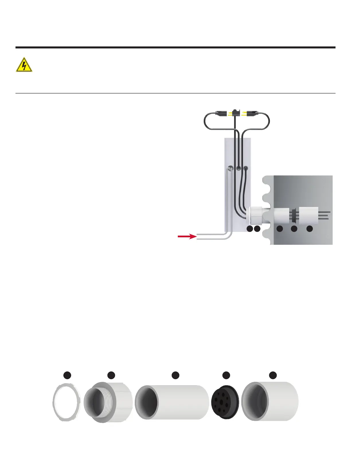
Run the direct burial power wires underneath the bottom of the
post as shown in the illustration to the right.
Note: Seal all conduits to prevent moisture and gases from
entering the post per local codes.
STEP 2: INSTALLING AN ALDERON RISER CONNECTION KIT
1. Determine location for access hole on the post. Drill access hole for the correct size terminal adapter (2.0" or 2.5" depending
on model / #2). Insert terminal adapter into access hole. On the inside of the post, use the lock nut (#1) to secure the terminal
adapter in place (use PVC cement to ensure proper bonding between the terminal adapter and post per local codes).
2. Insert PVC pipe (conduit / #3) into terminal adapter using appropriate cement for bonding.
3. Determine location on the riser to insert the conduit (2.0" or 2.5" depending on model). If your riser does not have a
pre-drilled hole for the conduit, you must drill a hole in the riser to accept the conduit. Insert conduit through the riser hole,
which is now attached with the post. Seal conduit to riser hole with silicone or per local codes.
4. Run the pump power, pump oat switch, and alarm oat switch cables through the PVC coupler (#5). Then continue through
the conduit and to the appropriate height inside the post for wiring. Take the 3-hole rubber grommet (#4) which has slits
next to the holes and insert cables, then insert the rubber grommet into the conduit.
5. Place the PVC coupler over the end of the conduit.
1 2 3 4 5
21 4 53
(Direct Burial Wires)

 Loading...