Alderon Industries™ - Leading Edge Control Products | 5
Mini Power Post™ Monitoring System - USER GUIDE
Features
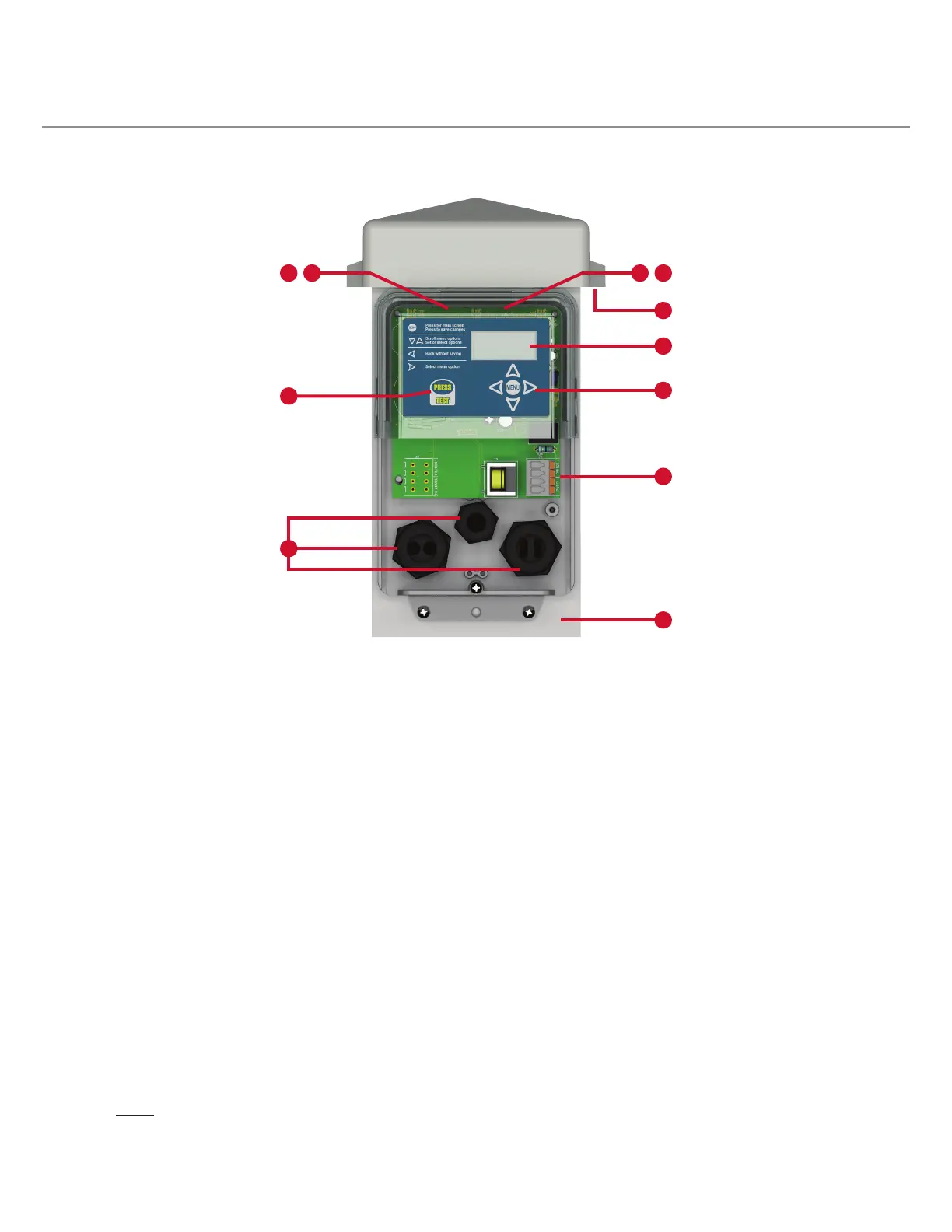
Refer to the illustration below to reference the feature descriptions provided.
(1) Power On Indicator - Green LEDs will illuminate inside the top
cover of the enclosure to indicate that the unit is powered on. Note:
The power on LED indicators can be disabled in system settings, see
page 21.
(2) Alarm Beacon - During an alarm condition, the green power on
indicator will turn off and alarm LEDs (various colors) will illuminate,
ashing inside the top cover of the enclosure, see pages 12-17.
(3) Pump Run Indicator - When the pump is running under normal
conditions, the blue LED indicator will illuminate inside the top cover
of the enclosure. Note: The pump run LED indicators can be disabled
in system settings, see page 21.
(4) System LED Indicators - Multiple color indicators will illuminate
inside the top cover of the enclosure for visual indication of various
system events and/or alarm conditions. See pages 12-17 for detailed
information of system events or alarm conditions.
(5) OLED Display Screen - Displays system functions in addition
to the visual indication provided by the LED indicators inside the top
cover of the enclosure.
(6) Menu Keypad - Toggle between the system functions, program
settings, or view all lifetime data stored.
(7) Test Pushbutton - Used for quick access to lifetime pump run
event counter statistic, test the alarm LEDs, or exit the menu system.
The system MUST be in an idle state (solid green LEDs) to perform
testing. When pressed, the event statistic is displayed, then the alarm
LEDs will cycle between red, green, blue, and off, see page 18.
(8) Quick Snap Terminal Block - A four-position terminal block is
included to make fast and easy connections for: system power and
pump power. These wires are tied in series and pre-installed at the
factory .
(9) Vented Post Cap - Allows airow to prevent the build up of
gases and condensation inside the post.
(10) QR Code (not shown) - Scan code on bottom enclosure cover
which directs you to alderonind.com where additional information can
be found for the Mini Power Post™.
(11) Cable Grips - Pre-installed, making it easy to run wire in and out
of the enclosure. The grips create a liquid and gas tight strain relief
connection when securely fastened.
(12) Pump Power Receptacle (not shown) - A female, 15A, pump
power receptacle is pre-installed. Available in 120VAC or 240VAC
models.
(13) Post - Provides wire routing access for system power and pump
power while protecting from water intrusion.
1 2 34
5
6
7
13
8
9
11

 Loading...