Alderon Industries™ - Leading Edge Control Products | 9
Mini Power Post™ Monitoring System - USER GUIDE
Testing
Make sure all steps of the installation and wiring process is
completed and there is power to the product.
STEP 1: TEST ALARM LEDs
Press the test pushbutton on the front of the enclosure, the
lifetime pump run event counter statistic should display, then
alarm LEDs should illuminate while cycling between red, green,
blue, and off. The OLED screen should display a TESTING
(COLOR) event to match the respective LEDs after the event
statistic is displayed.
Note: When activated, system test will exit the menu system
without saving and disable the menu system. Any events that
are active while system test starts will not be shown, but will be
tracked normally. Any newly activated event will deactivate the
system test event.
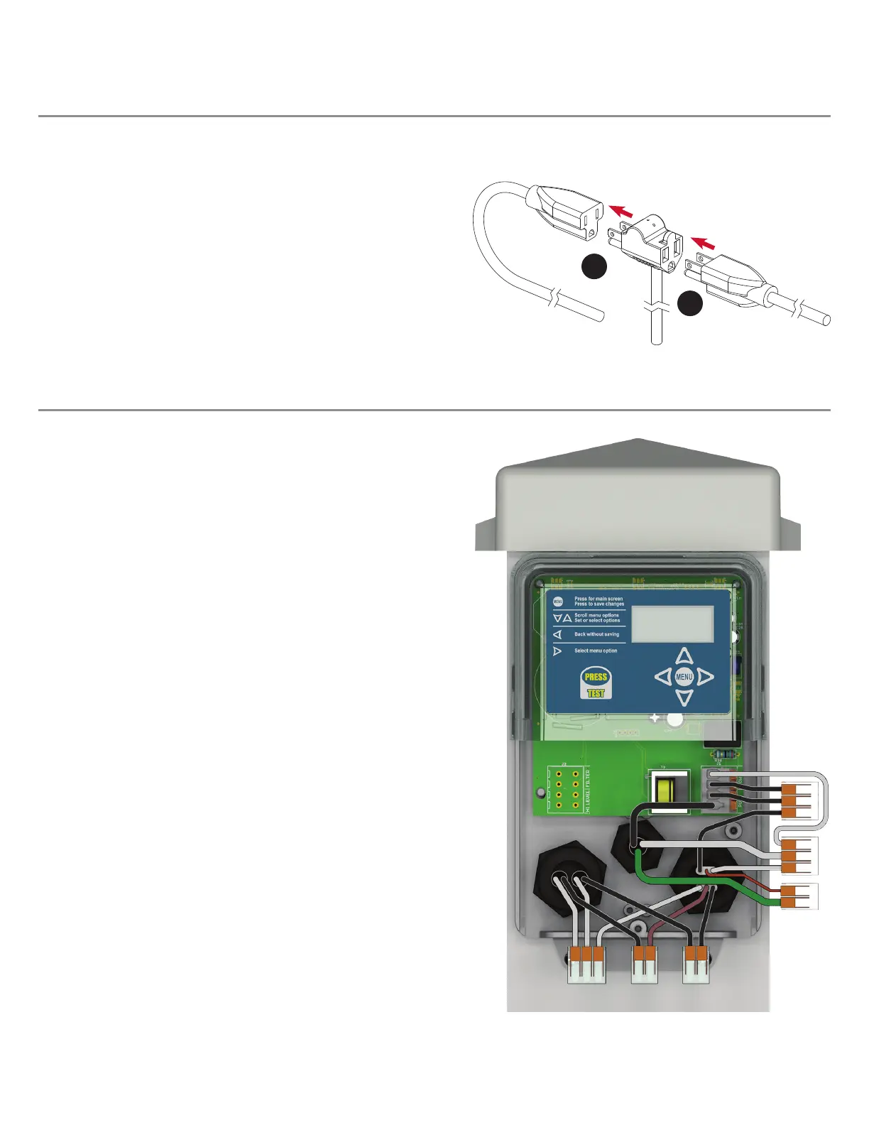
STEP 2: TEST PUMP AND PUMP FLOAT SWITCH
The pump power is factory wired to the terminals and attached
in series to the alarm power, terminated by Wago connectors.
Make sure the tank has water to perform the pump and pump
oat switch testing. Activate the pump oat switch, the blue
LEDs should illuminate and the OLED screen should display a
PUMP RUN event and the pump amps are displayed.
Note: Record the pump amps if changing the high amp level
setting in the main menu. See page 21 for detailed information.
STEP 3: RECOMMENDED SYSTEM SETTINGS
Alderon™ recommends changing the factory settings for: high
amp level, extended pump run time, and gallons per minute.
See page 21 for detailed information.
STEP 4: TEST WEEKLY
To ensure the product is functioning properly, test once a week.
Note: If using a remote alarm panel, high level alarm oat switch, and/or lter switch;
refer to the product instructions for additional installation and testing information.
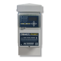
STEP 2: PIGGYBACK PLUG CONNECTIONS
1) Plug the male end of the piggyback plug on the pump switch
power cable into the pre-installed female power receptacle
inside the post (2A).
2) Plug the male end of the pump power cable into the female
end of the piggyback plug on the pump switch power cable
(2B) from step 2-1.
Note: The installation example shown is for a 120VAC system,
use the same process when connecting 240VAC piggyback
power cables.
2B
2A
Pump Switch
Piggyback Plug
Power Cable
Pump
Power Cable
(120VAC Example Shown)
Pre-Installed
Female
Power Receptacle
Wiring (continued)

 Loading...