Alderon Industries™ - Leading Edge Control Products | 31
Mini Power Post™ Monitoring System - USER GUIDE
General Operation
The Mini Power Post™ Monitoring System serves as a junction box equipped with LED indicators (various colors) which is
connected to a remote alarm panel. The top of the enclosure cover changes color along with system function displayed text on
the OLED screen for easy troubleshooting information. View program settings and data such as: pump cycle counts, elapsed
time, total gallons pumped, alarm conditions, and more. The applications are not limited to what is listed in this user guide.
Follow all individual instructions for oat switches and accessories used with the Mini Power Post™ Monitoring System.
The following application can be found in this user guide: Septic Tank Monitoring using Pump, Control, and Filter Switches with
a Versa’larm™ indoor alarm panel.
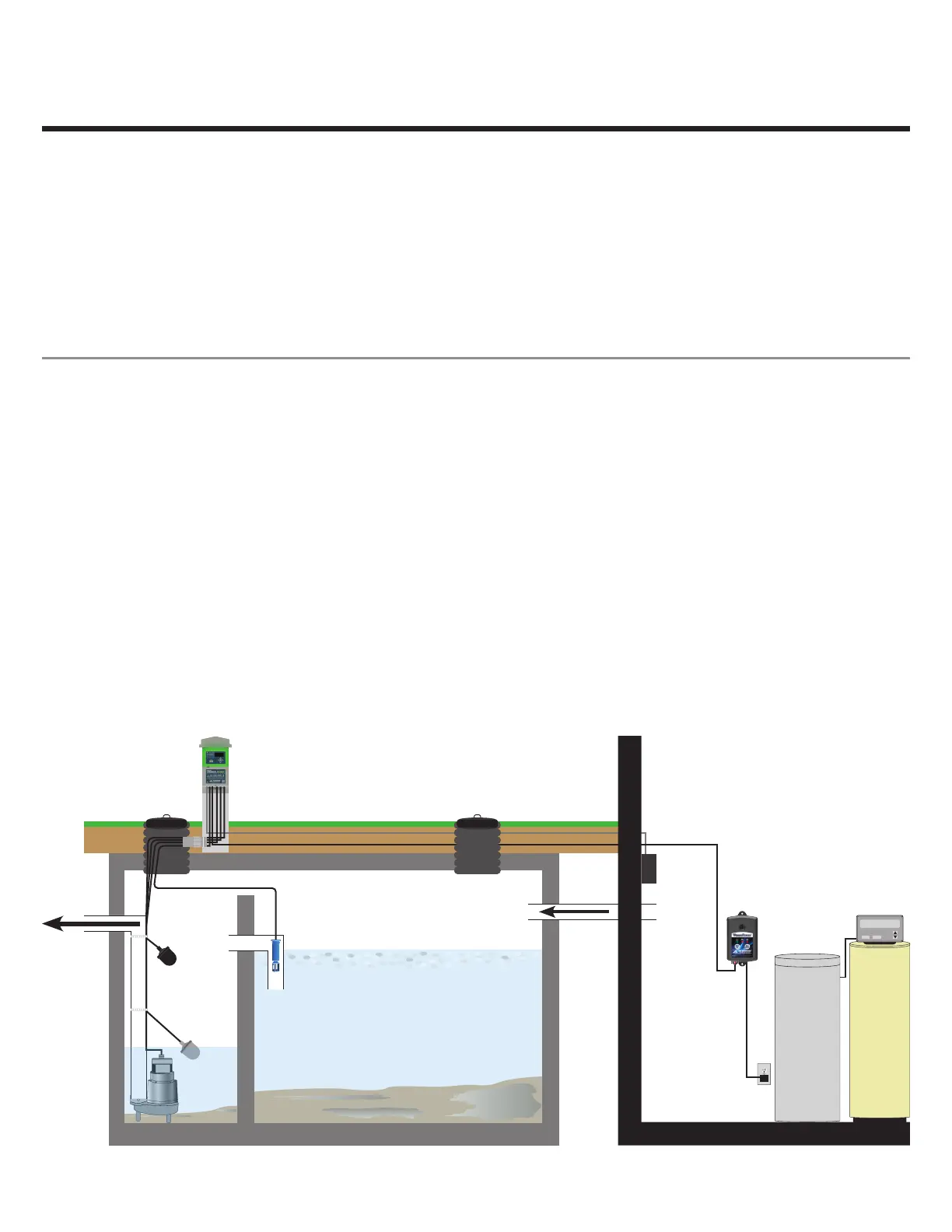
Septic Tank Monitoring | Pump, Control, and Filter Switch Operated with Remote Alarm
The diagram below displays the typical setup for septic tank monitoring. The setup includes: Mini Power Post™ Monitoring
System, Versa’larm™ indoor alarm, pump oat switch, alarm oat switch, and lter switch. The Mini Power Post™ is installed
into the ground and attached to the septic tank riser. The pump is plugged into the piggyback plug of the pump oat switch.
When the pump oat switch is actuated, the pump will turn on and turn back off when the pump oat switch is deactivated.
The alarm oat switch and lter switch are wired to a pair of Wago connectors inside the Mini Power Post™ enclosure along
with a customer supplied sensor wire coming from a set of terminals on the Versa’larm™ indoor alarm panel.
When the alarm oat switch is actuated, the alarm LED will illuminate and the buzzer will annunciate on the indoor alarm
panel. The alarm condition will stay on until the alarm oat switch is deactivated. If the silence pushbutton on the indoor alarm
is pressed during an alarm condition, then the alarm LED will remain on and the buzzer will silence. The silence condition will
reset when the alarm oat switch deactivates.
When the lter switch is actuated, the alarm LED will illuminate and the buzzer will annunciate on the indoor alarm panel. The
alarm condition will stay on until the efuent lter has been serviced/cleaned and the lter switch is deactivated. If the silence
pushbutton on the indoor alarm is pressed during an alarm condition, then the alarm LED will remain on and the buzzer will
silence. The silence condition will reset when the lter switch deactivates.
Use the menu keys to view data for: pump cycle counts, pump elapsed time, total gallons pumped, and much more.
5:05
PM
71%
REGENERATION
MENU ENTER
Mini Power Post™
Monitoring System
Alarm
Float
Pump
Switch
Septic
to
Drain Field
House
to
Septic
Filter
Switch
Versa’larm™
Indoor Alarm Panel

 Loading...