Appendix B
CE Conformity
B–5
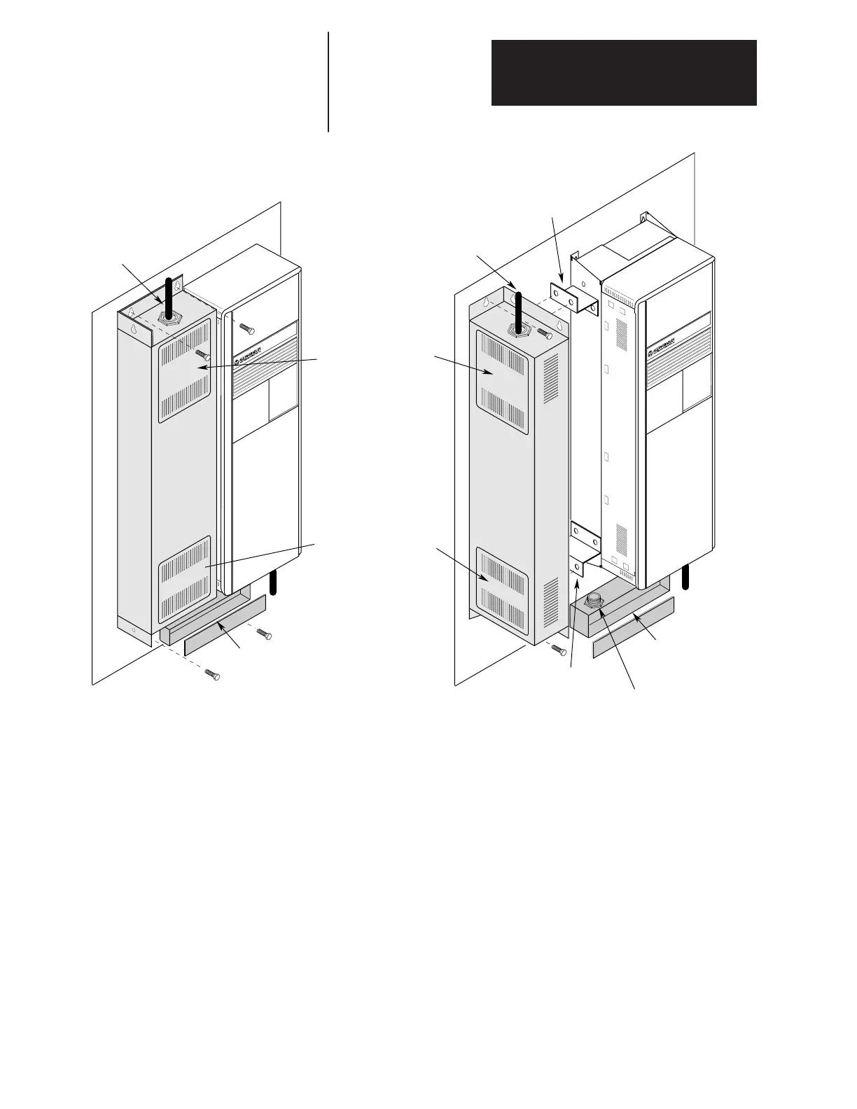
1336 FORCE
Through-the-Wall Mounting)
Frames D & E
2
1336 FORCE
(Conventional Mounting)
Frames D & E
2
Conduit Box
1
To Motor
1
Access Panel and
Input Terminal Block
Lower Access Panel
Filter Mounting
Bracket
Filter Mounting
Bracket
Important: Drive and filter must be
mounted to a common back plane with
a positive electrical bond. Spacing is
determined by Conduit Box.
Three-Phase
Input
1
To Motor
1
Three-Phase
Input
1
Conduit Box
1
Nipple/Fitting
1
Input power (source to filter) and output power (filter to drive and drive to motor) wiring must be in conduit or have shielding/armor with equivalent attenuation.
Shielding/armor must be bonded to the metal bottom plate. See requirements 6 & 7 on page E–1.
2
Refer to the Filter Selection table on page B–2 for frame references and corresponding catalog numbers.

 Loading...


