Chapter 2
Installation/Wiring
2–26
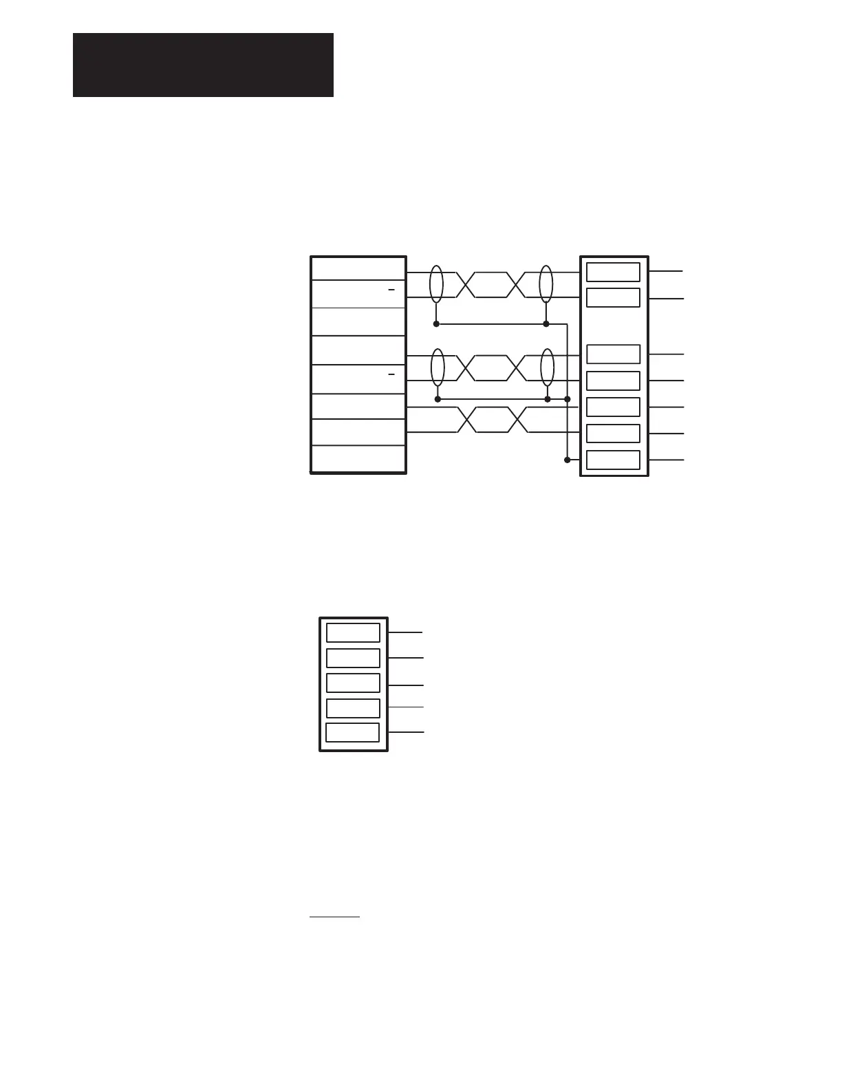
Encoder Connections The Encoder connections are made at terminal block TB10 on the Main
Control Board as detailed in Figure 2.12.
Figure 2.12.
Encoder Connections
Encoder
Shield
Common
+12 Volts
Encoder B
Encoder B
Encoder A
Encoder A
6
7
5
4
3
1
2
TB10
Drive to Drive Communication
The TB11 connector on the Main Control Board (Figure 2.13) is used to
connect the Drive to Drive Communication Interface.
Figure 2.13.
Drive to Drive Connections
4
3
5
(SHD)
(C_L)
(V+)
2
RTN (V–)
TB11
1
(C_H)
Drive to Drive Setup – The hardware setup for Drive to Drive (D2D)
consists of a shielded cable going from CN+ and CN– between the drives.
The shields are to be tied together and grounded at one point (TE).
TB11–3 SHD is an open connection and is used to tie ground wire together.
A wire must go from TB11–3 to TE Bus. Place a 120
Ω terminating
resistor on both ends of the cable. You must supply the 8 –18 VDC that
powers the D2D. Figure 2.14 shows a typical D2D connection using the
required
Allen–Bradley Isolation Board. Recommended cable is Drive to
Drive cable (A–B 1485–C–PI–C) which is available in 50, 150, 300 and
600 meter lengths.

 Loading...


