Chapter 2
Installation/Wiring
2–31
Analog Outputs – There are (2) analog outputs from the Standard
Adapter Board that have a range of + 10V and (1) 4–20 mA output with a
digital resolution of 12 bits.
Discrete Outputs
Fault outputs from the 1336 FORCE are supplied at terminal block TB7 on
the Standard Adapter Board. Fault outputs provide warning or fault signals
based on Drive Programming.
Fault NC
Fault Com
Fault NO – A form C, NO/NC relay contact on the Standard Adapter
Board programmed to provide external warning or fault change–of–state
signals.
Contact Ratings = 2A @ 115 VAC
2A @ 30 VDC
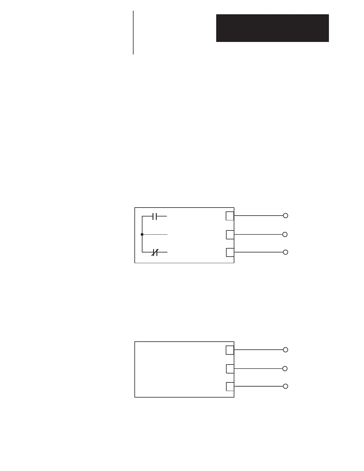
Figure 2.19
Typical Digital Output (Standard Adapter)
Fault Com (Digital Out)
Fault NC (Digital Out)
6
5
4
TB7
Fault NO (Digital Out)
Pulse Input
The pulse input lets an external source provide the drive with a digital
reference or trim signal. Pulse input is a differential input with a maximum
frequency of 100 kHz.
Figure 2.20
Pulse Input Connection
5 – 12V Pulse Input
100 kHz max.
12
13
14
TB5
TE
Unidirectional
The pulse input can be useful if you have a system with multiple drives and
you want encoder magnetic pickup or other drives that provide a pulse to
supply the reference for additional drives. You could use this reference to
ensure that all drives run at the same speed or to ensure that the speed of
the other drives is related to the speed of the reference.

 Loading...


