Chapter 2
Installation/Wiring
2–42
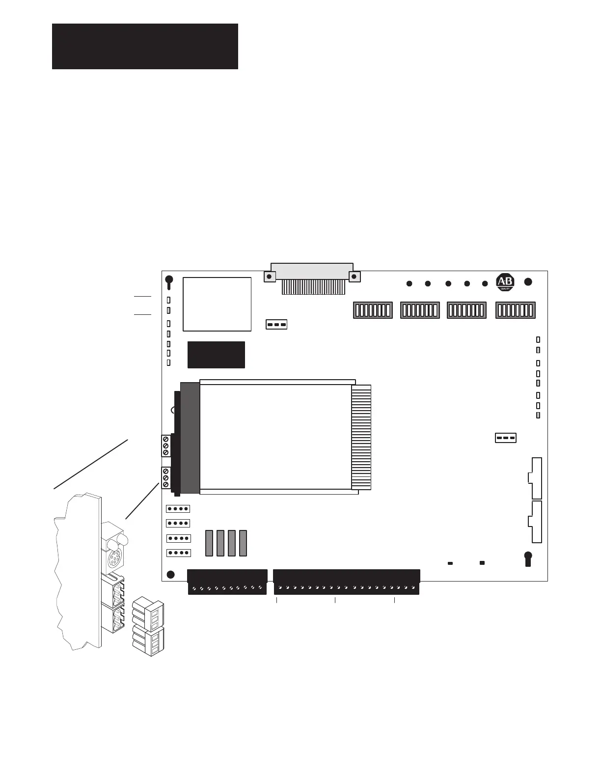
PLC Communication Adapter Board Control and Signal Wiring – When installing and wiring the PLC
Communication Adapter Board, you need to deal with the following issues:
• Control and Signal Wiring
• Jumper Settings for I/O Circuits
If your 1336 FORCE Drive is equipped with a PLC Comm Adapter Board,
terminal blocks TB20 & TB21 located at the bottom center of the PLC
Comm Board (Figure 2.29) are used for control and signal wiring (Drive
Permissives). Connector TB21 provides the interface for Analog Input and
Output reference signals as detailed in Figure 2.30.
Figure 2.29.
PLC Comm Board Connections
AP
Status
LANGUAGE
MODULE
DP Status
1
CH A High
J5
TP1
Port 1
DOMINO
ADAPTER
RIO
Channel A
Communication Modes
U2 U3 U4 U5
10
TB20
TB21
119
CH A Low
CH B Low
CH B High
D3
D6
D8
D10
D12
D13
D14
D15
CH A
Status
CH B
Status
J7
D1
D2
Port 2
TP2
TP3
TP4
TP5
ADC InputsDAC Inputs
J1
Main Control
Interface
Drive Permissives
J4
J3
120 V
RIO
Channel B
BRAM
Enable
Ref
D4
D5
Fault Out
Ext Fault
D7
Norm Stop
Motor Thermo
D9
Drive Enable
D11
24 V
120 V 24 V
120 V 24 V
120 V 24 V
J11
J10
J9
J8
Drive En
M Therm
N Stop
X Flt
EN DIS
Fuse
1 – 4
TP24
+10V Ref
TP25
–10V Ref
↑
ON
↑
ON
↑
ON
↑
ON
DGND +5V +15V –15VAGND
NOTE: For more information on the PLC Communication Board
including LEDs and Jumpers, refer to the PLC Communication User
Manual 1336 FORCE 5.13.
CHANNEL A
SHIELD
CHANNEL B
2
1
SHIELD
2
1
The maximum and minimum wire size accepted by TB20, TB21, Channel
A and Channel B is 3.3 and 0.06 mm
2
(12 and 30 AWG). Maximum
torque for these terminal blocks is 0.79 N–m (7 lb. – in.). Only copper
wire may be used.

 Loading...


