Chapter 2
Installation/Wiring
2–43
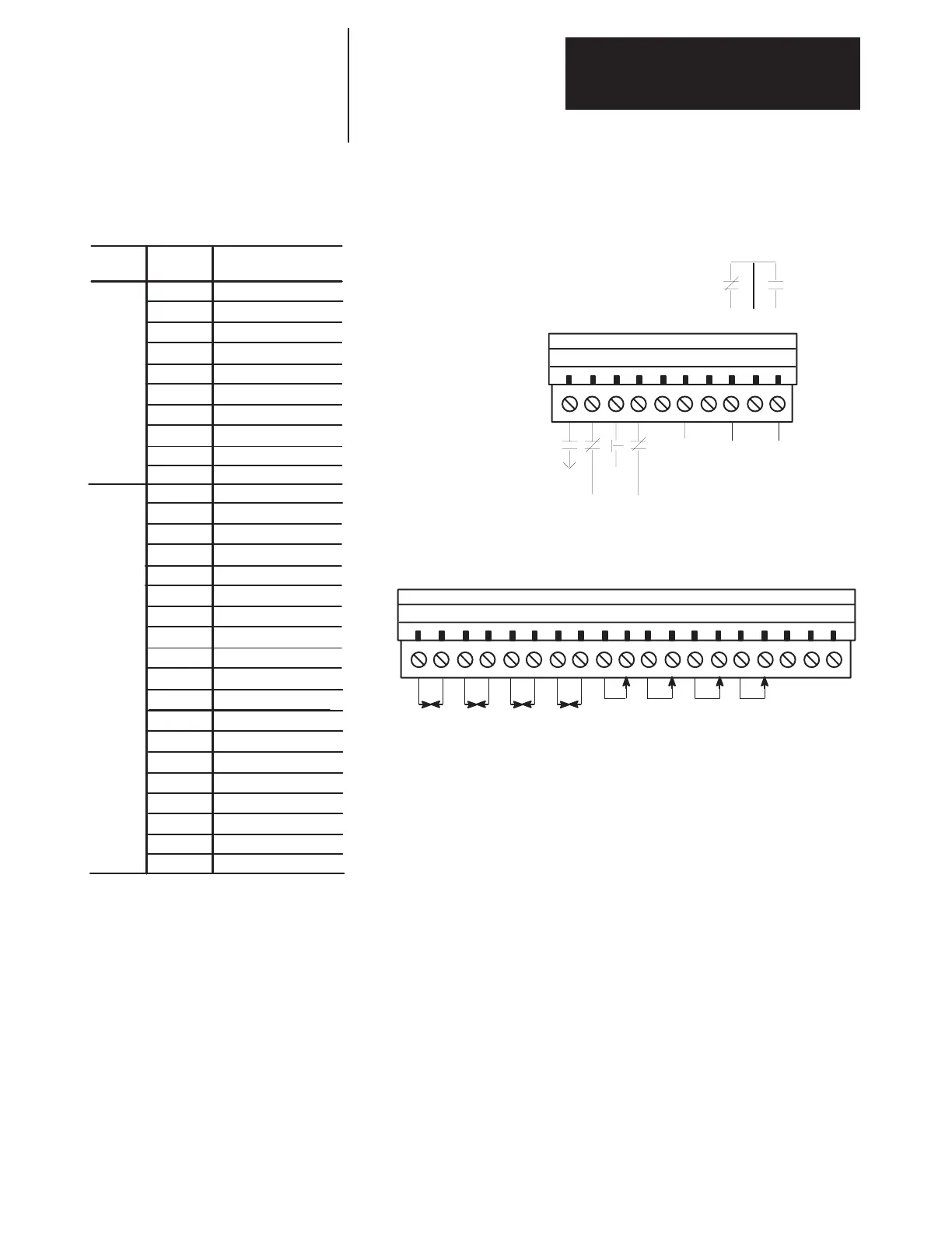
Figure 2.30.
Reference Signal Connections (PLC Comm Adapter)
TB20
1 2345678910
TB21
1 234567891011 12 13 14 15 16 17 18 19
Common
Terminal
Block
Terminal
Number(s)
TB20
Signal
1 Drive Enable (NO)
2
Motor Thermoguard (NC)
3
Normal Stop (NC)
Analog
Out 1
Analog
Out 2
Analog
Out 3
Analog
Out 4
4
5
6
External Fault (NC)
Input Common
7
8
9
Fault Output (NC)
Fault Output (COM)
10
Fault Output (NO)
TB21
1
OUT 1
2
COM 1
3
COM 2
4
5
6
7
8
9
10
OUT 2
OUT 3
COM 3
OUT 4
COM 4
IN 1+
IN 1–
11
12
13
14
15
16
IN 2+
IN 2–
IN 3 +
IN 3–
IN 4+
IN 4 –
17
18
19
+10V
COM
–10V
Drive
Enable
Motor
Thermo
Norm
Stop*
Ext
Fault
Fault
Relay
Analog
In 1
Analog
In 2
Analog
In 3
Analog
In 4
+10 –10
Comm
Note: If using a pot as an input 2.5KΩ min.
*Refer to Parameter 58 description for explanation of modes
Pin jumper J3 on the PLC Communication Adapter Board Enables or
Disables the BRAM (Battery Backup RAM) Write function as follows:
Jumpered 1 – 2 = Enabled
Jumpered 2 – 3 = Disabled
The PLC Communication Adapter Board 120V/24V jumper settings for I/0
circuits (J8 – J11) are detailed in the 1336 FORCE PLC Communications
Adapter User Manual Publication 1336 FORCE– 5.13.
Switch Settings – There are DIP switches and jumpers located on the PLC
Communications Adapter Board that have been preset at the factory.
Communication is received through Channels A and B. This
communication protocol is defined through SW U2 – U5. If you need to
reconfigure the switches or jumpers consult the 1336 FORCE PLC
Communications Adapter User Manual.

 Loading...


