Chapter 2
Installation/Wiring
2–30
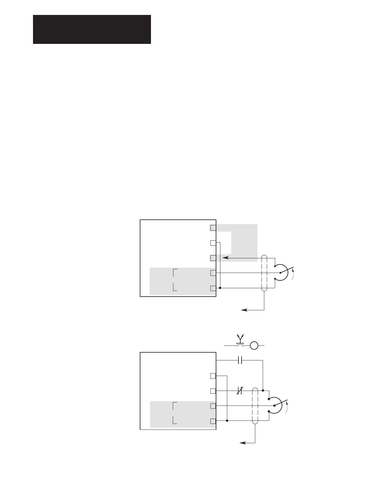
Analog Inputs – There are (2) analog inputs to the Standard Adapter
Board (Figure 2.18) that have a range of ±10V, (1) 4–20 mA analog input
and (1) pulse source input with a digital resolution of 12 bits. These inputs
are differential inputs with noise rejection filtering.
Each input has a gain and offset adjustment. The A/D converter is a 12 bit
device where an input value of +10V will result in a digital value of 2048.
Likewise, an input value of –10V will result in a digital output value of
–2048.
NOTE: Analog input parameters must be linked to a velocity reference
parameter as well as a scaling and offset parameter for an analog input to
function.
NOTE: Refer to Chapter 4, Startup, for Analog I/O configuration
information.
Figure 2.18
Analog Input Connections
Typical Connections for Unidirectional Operation
Typical Connections for Bidirectional Operation
COM (POWER SUPPLY COMMON)
IN + (ANALOG IN)
+ 10V DC (POWER SUPPLY)
IN (ANALOG IN)
REFERENCE POT
2.5 kΩ MINIMUM
TB5
1
– 10V DC (POWER SUPPLY)
3
ADC
REVERSE
FORWARD
R
Reverse
Reverse
Relay
Forward
6
0 to
+/–10V
7
8
2
COM (POWER SUPPLY COMMON)
IN + (ANALOG IN)
+ 10V DC (POWER SUPPLY)
IN (ANALOG IN)
2
6
REFERENCE POT
2.5 kΩ MINIMUM
TB5
Connect to
Either 1 or 3
(ONLY ONE)
1
– 10V DC (POWER SUPPLY)
3
ADC
7
8
0 to
+/–10V

 Loading...


