Publication 1734-UM006B-EN-P - August 2005
Install the Module 2-3
Install the Mounting Base
and Wiring Base Assembly
The wiring base assembly (1734-TB or 1734-TBS) consists of a
mounting base (cat. no. 1734-MB) and a removable terminal block
(catalog number 1734-RTB or 1734-RTBS).
You can install the assembly, or just the mounting base. To install the
mounting base and wiring base assembly on the DIN rail, proceed as
follows.
1. Position the mounting base and wiring base assembly vertically
above the installed units (adapter, power supply or existing
module).
2. Slide the mounting base down so that the interlocking side
pieces engage the adjacent module or adapter.
ATTENTIO
POINT I/O is grounded through the DIN rail to chassis
ground. Use zinc-plated, yellow-chromated steel DIN
rail to assure proper grounding. The use of DIN rail
materials (such as aluminum and plastic) that can
corrode, oxidize, or are poor conductors can result in
improper or intermittent grounding.
Secure DIN rail to mounting surface approximately
every 200 mm (7.8 inches).
24VDC
Source
Output
Module
Status
Network
Status
1734
OB4E
NODE:
0
1
2
3
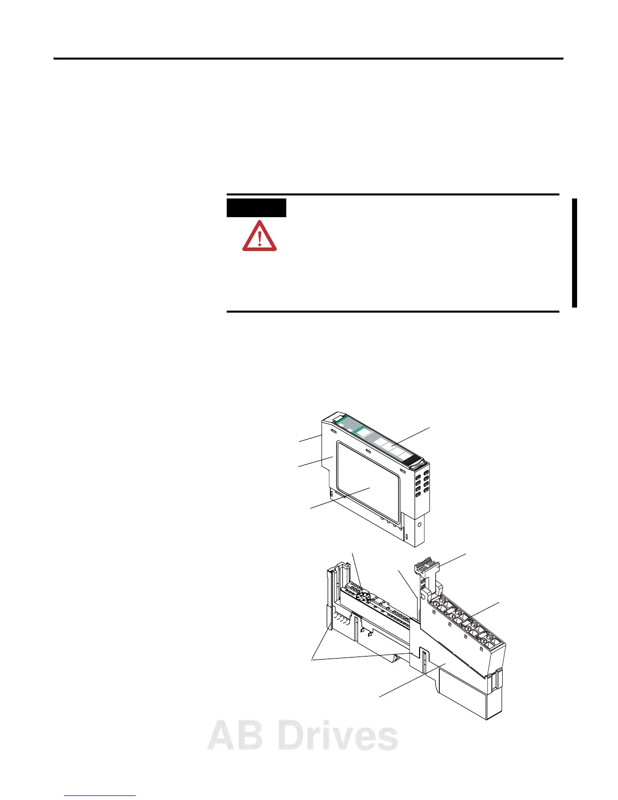
Mounting Base
Mechanical Keying
(orange)
Module Wiring Diagram
1
Module Locking Mechanism
Insertable I/O Module
RTB Removing Handle
Removable Terminal Block (RTB)
DIN Rail Locking Screw
(orange)
Slide-in Writable Label
Interlocking Side Pieces
41825
AB Drives
 Loading...