Publication 1734-UM006B-EN-P - August 2005
About the Modules 1-5
Period / Rate Mode
The Period/Rate Mode will return an incoming frequency and a total
accumulated count to the POINTBus, by g
ating an internal 5MHz
internal clock with an external signal.
This mode determines the frequency and total number of input pulses
by counting the number of internal 5MHz clock pulses over a
user-specified number of input signal pulses. At the end of the
specified number of pulses, the module returns the frequency
(0 - 1 MHz).
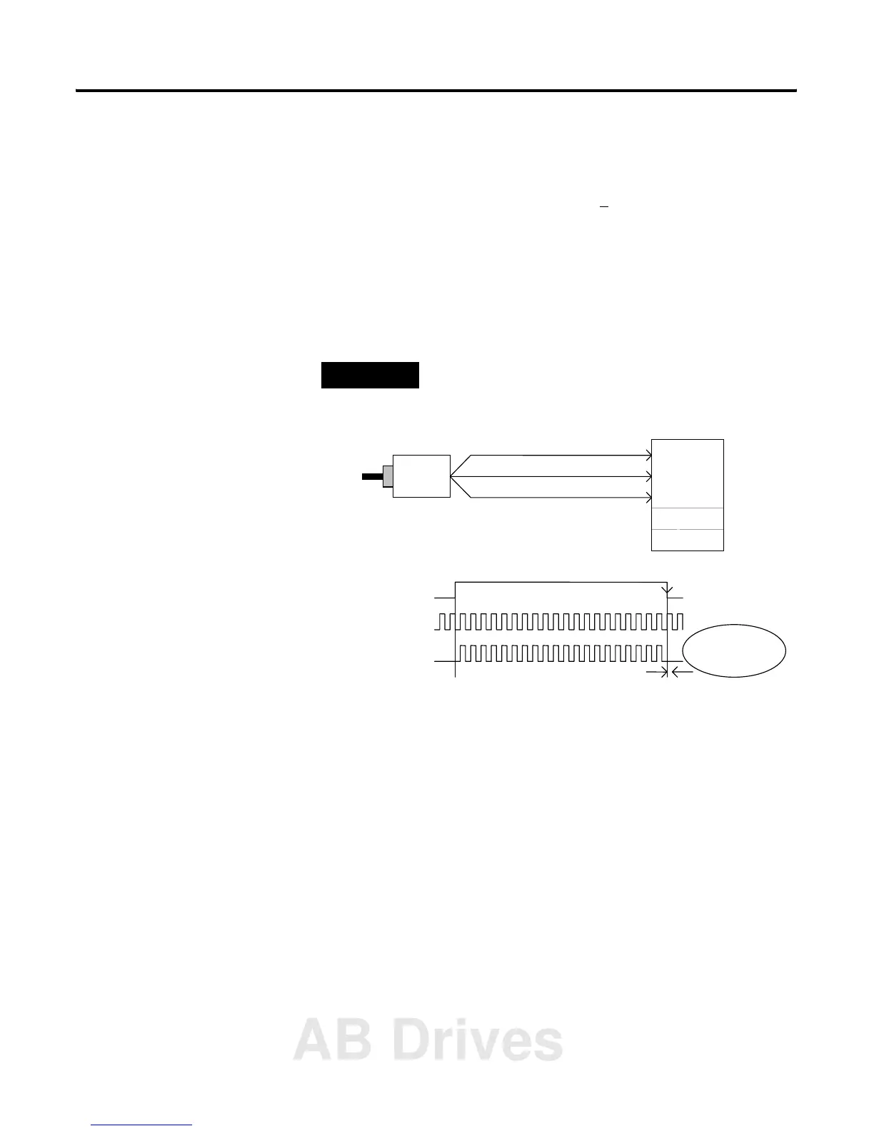
EXAMPLE
Example of Period/Rate Mode
As the frequency of the incoming pulse train at the Z (Gate/Reset)
terminal increases, the number of sampled pulses from the 5 MHz
clock decreases. Since accuracy is related to the number of pulses
received over the sample period, the accuracy decreases with
increasing frequencies at the Gate/Reset terminal. Refer to the
following Scaling table.
A ( Not Used )
B ( Not Used )
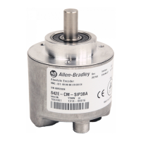
Encoder / Pulse Generator
1734-IJ/IK
Input A
Input B
Z Input ( Pulse )
5 MHz Internal
(Gate / Reset )
Input Z
Z
Accumulated Count
1
Scalar
5 MHz Clk
Sampling Clock
ssumes symmetrical pulse, 50% duty cycle, so Period = Sample Time On X 2 {On & Off}
10 20
requency = 1 / Period If Count = 20, Scalar = 1, and Clock Period = ( 1 / 5 MHz )
requency = 1 / [ ( 20 / 1 ) X ( 1 / 5 MHz ) X 2 ] = 125 kHz
Frequency
Updated Here
AB Drives
 Loading...