Publication 1734-UM006B-EN-P - August 2005
Install the Module 2-5
Install the Module
Install the module before or after base installation. Make sure that you
correctly key the mounting base before installing the module into the
mounting base. In addition, make sure you position the mounting
base locking screw horizontal, as referenced to the base.
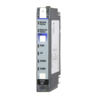
1. Using a bladed screwdriver, rotate the keyswitch on the
mounting base clockwise until the number required for the type
of module you are installing aligns with the notch in the base.
1734-IJ - Position 2
1734-IK - Position 2
2. Make sure the DIN rail locking screw is in the horizontal
position.
You cannot insert the module if you unlock the locking
mechanism.
3. Insert the module straight down into the mounting base,
and press to secure.
WARNING
When you insert or remove the module while
backplane power is on, an electrical arc can occur.
This could cause an explosion in hazardous location
installations.
Be sure that power is removed or the area is
nonhazardous before proceeding. Repeated electrical
arcing causes excessive wear to contacts on both the
module and its mating connector. Worn contacts may
create electrical resistance that can affect module
operation.
Turn the keyswitch to align
the number with the notch.
Notch
(position 3 shown)
44009
Make sure the DIN rail
locking screw is in the
horizontal position.
44010
AB Drives
 Loading...