Rockwell Automation Publication CNET-UM001F-EN-P - February 2018 71
Table 16 - Example Tag Names
1
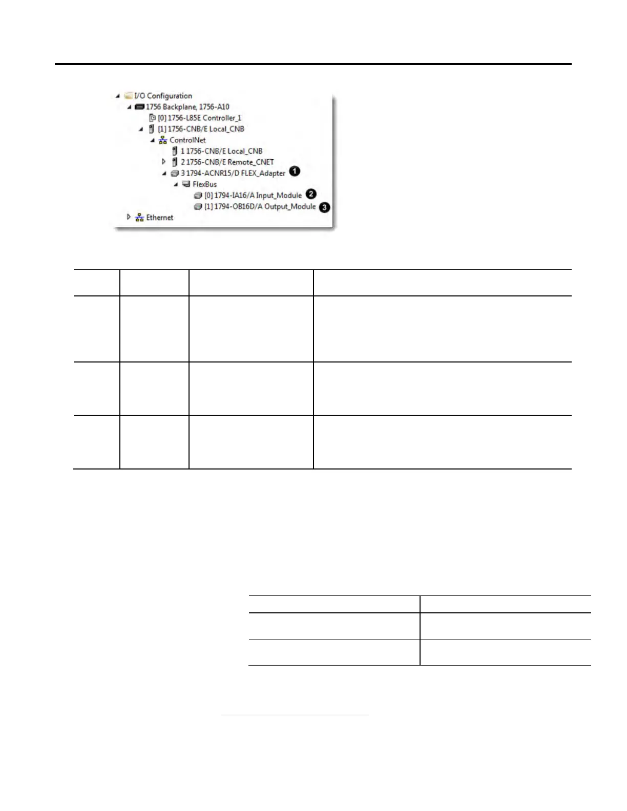
Example Example Tag Module Example Tag Names Created by Logix Designer Software
1 Example 1 Remote 1794-ACN15
adapter FLEX_adapter
FLEX_adapter:I
FLEX_adapter:I.SlotStatusBits
FLEX_adapter:I.Data
FLEX_adapter:O
FLEX_adapter:O.Data
2 Example 2 Remote 1794-IA16
Input_module in slot 1
rack-optimized connection
FLEX_adapter:1:C
FLEX_adapter:1:C.Config
FLEX_adapter:1:C.DelayTime_0
FLEX_adapter:1:I
3 Example 3 Remote 1794-OB16D
Output_module in slot 2
rack-optimized connection
FLEX_adapter:2:C
FLEX_adapter:2:C.SSData
FLEX_adapter:2:O
FLEX_adapter:2:O
You need to verify that the controller can communicate with the devices that
you have just configured.
To validate connections, perform this procedure.
1. Determine if communication has been established with the devices.
If a warning symbol Then
Appears over the I/O Configuration
folder
The controller cannot communicate with
the device.
Does not appear over the I/O
Configuration folder
The controller can communicate with
the device and connections are valid.
1
The tags listed are not a complete list of the tags created for each module type. For
a full list of the tags created for each module, see the Tag Monitor tool in the Logix
Designer application.
Connections
 Loading...


