Rockwell Automation Publication MOTION-UM002E-EN-P - June 2016 59
Configure an Articulated Independent Robot Chapter 4
Configuration Parameters
Logix Designer application can be configured for control of robots with
varying reach and payload capacities. As a result, it is very important to know
the configuration parameter values for your robot including:
•Link lengths.
• Base offsets.
• End-effector offsets.
The configuration parameter information is available from the robot
manufacturer.
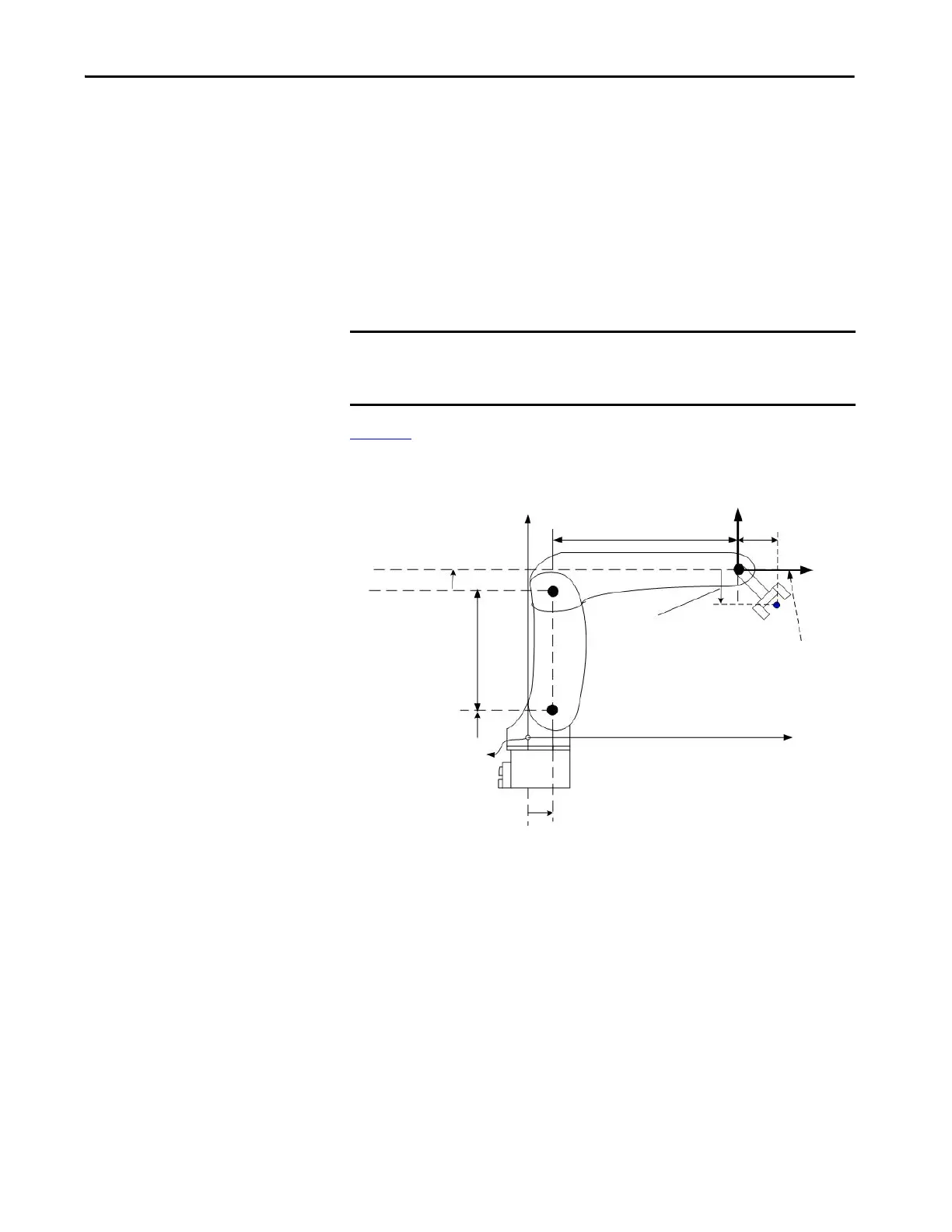
Figure 13
illustrates the typical configuration parameters for an Articulated
Independent robot.
Figure 13 - Typical Configuration Parameters for an Articulated Independent Robot
IMPORTANT Verify that the values for the link lengths, base offsets and end-effector
offsets entered into the Configuration Parameters dialog use the same
measurement units.
If the robot is two-dimensional, then X3b and X3e are X2b and X2e respectively.
X3e2 = 1.5 inches
L2 = 12 inches X1e = 2 inches
L1 = 12 inches
X1b = 3.0 inches
Robot Origin
-X3e1 = 3.0 inches
Tool reference frame
X3
X3b = 4.0 inches
X3e = -X3e1 + X3e2
X3e = -3 + 1.5
X3e = -1.5 inches

 Loading...


