32 Rockwell Automation Publication MOTION-UM002E-EN-P - June 2016
Chapter 2 Configure a Cartesian Coordinate System
Program an MCLM
Instruction
The following are the steps to program and test an MCLM instruction.
1. Configure motion axes in Logix Designer application.
The maximum number of axes that can be associated with one
Coordinate System is limited to three axes.
2. Create a Coordinate System Tag
The number of Coordinate System tags that can be created is 32. This
number is based on the fact that a maximum of 32 axes can be assigned
to a motion group and in the current implementation. Because only one
motion group can be created, the number of axes that can be created is
32.
3. Program an MCLM.
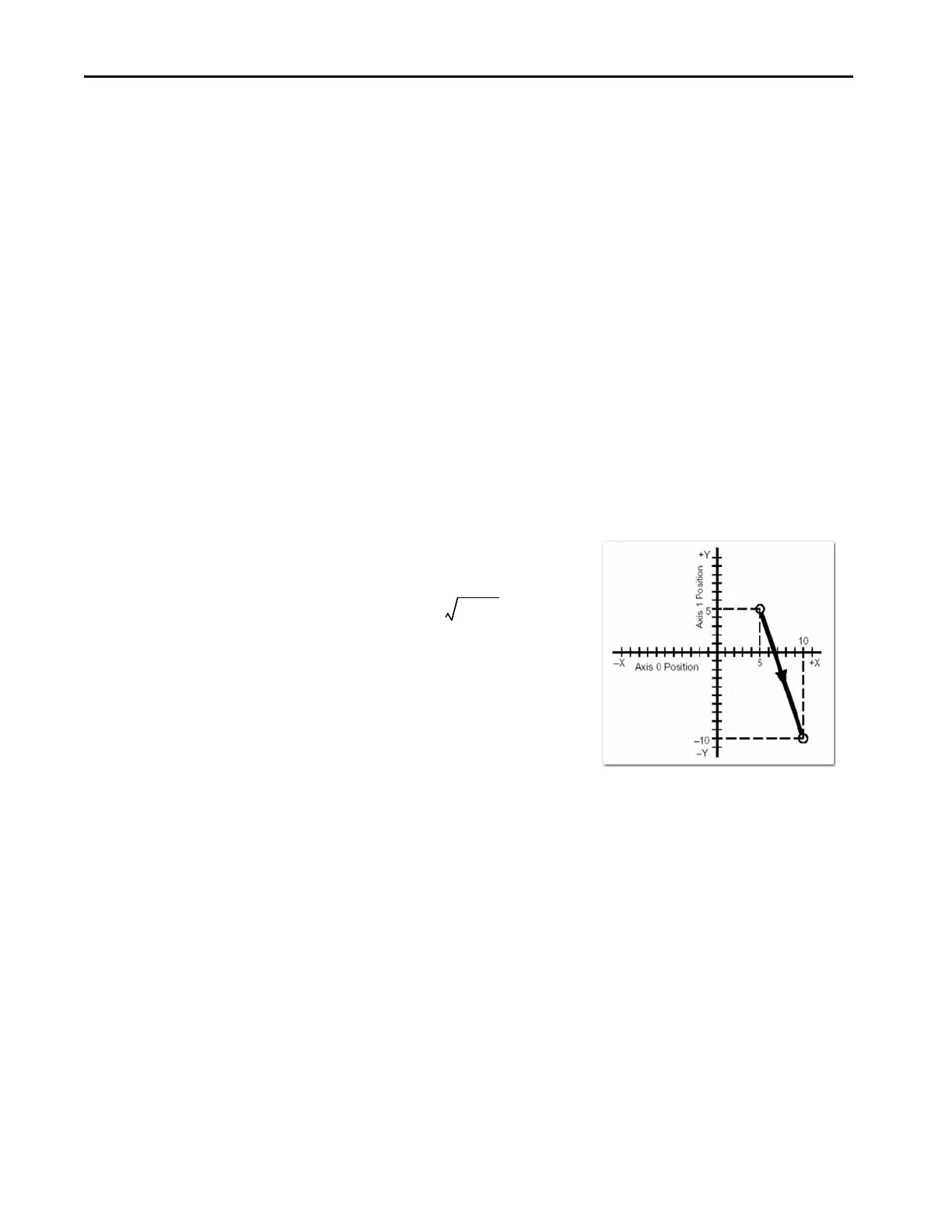
The Motion Coordinated Linear Move (MCLM) instruction performs
a linear move by using up to three axes in a Cartesian coordinate system.
As with all moves, you must specify, for example, absolute or
incremental, or speed. Speed is based on the vector move distance as
shown in this figure.
One dimension array determines the position. The coordinate system
selected determines array length. For a (2) Axis Cartesian System, each
endpoint requires (2) words; for a (3) Axis Cartesian System, each axis
requires (3) words. We create a position array shortly for clarification.
An array can consist of multiple endpoint coordinates that multiple
coordinated move instructions can use.
Blended Moves and
Termination Types
To blend two MCLM or MCCM instructions, start the first one and queue
the second one. The tag for the coordinate system gives you two bits for
queueing instructions.
•MovePendingStatus
• MovePendingQueueFullStatus

 Loading...


