64 Rockwell Automation Publication MOTION-UM002E-EN-P - June 2016
Chapter 4 Configure an Articulated Independent Robot
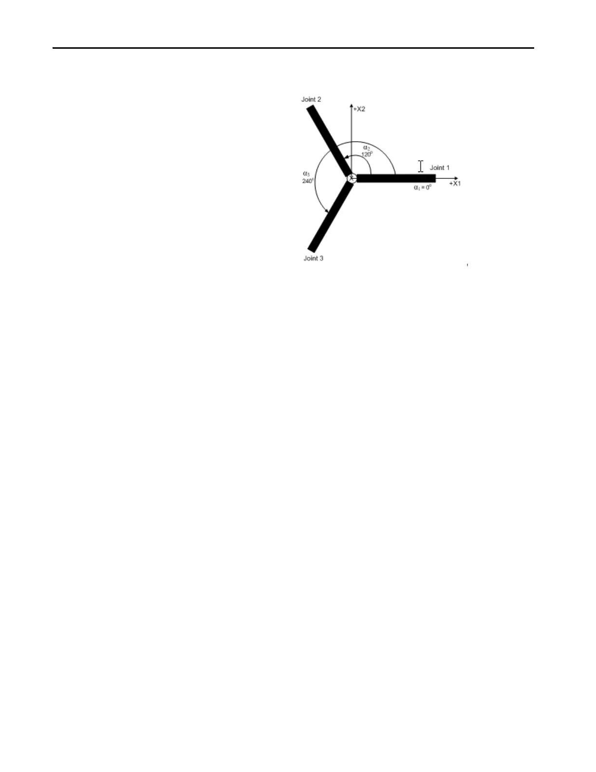
Establish the Reference Frame for a Delta Three-dimensional Robot
The reference frame for the Delta geometries is at the center of the top fixed
plate. Joint 1, Joint 2, and Joint 3 are actuated joints. If you configure the Delta
coordinate system in Logix Designer application with the joints homed at 0 in
the horizontal position, then L1 of one of the link pairs is aligned along the X1
positive axis as shown. Moving in the counter clockwise direction from Joint 1
to Joint 2, the X2 axis is orthogonal to the X1 axis. Based on the right hand
rule, X3 positive is the axis pointing up (out of the paper).
Calibrate a Delta Three-dimensional Robot
Use these steps to calibrate your robot.
1. Obtain the angle values from the robot manufacturer for J1, J2, and J3 at
the calibration position. These values are used to establish the reference
position.
2. Move all joints to the calibration position by either jogging the robot
under programmed control, or manually moving the robot when the
joint axes are in an open loop state.
3. Do one of these:
a. Use a Motion Redefine Position instruction (MRP) to set the
positions of the joint axes to the calibration values obtained in step 1.
b. Set the configuration value for the joint axes home position to the
calibration values obtained in step 1 of this procedure and execute a
Motion Axis Home instruction (MAH) for each joint axis.
4. Move each joint to an absolute position of 0.0. Verify that each joint
position reads 0° and that the respective L1 is in a horizontal position. If
L1 is not in a horizontal position, then see the alternate method for
calibrating a Delta three-dimensional robot.

 Loading...


