Rockwell Automation Publication MOTION-UM002E-EN-P - June 2016 77
Configure an Articulated Independent Robot Chapter 4
When the right-hand link L1 moves in the clockwise direction (looking down
on the robot), joint J1 is assumed to be rotating in the positive direction. When
the right-hand link L1 moves counterclockwise, joint J1 is assumed to be
moving in the negative direction.
When left-hand link L1 moves in the clockwise direction, joint J2 is assumed
to be moving in the negative direction. When the left-hand link L1 moves in
the counterclockwise direction, joint J2 is assumed to be rotating in the
positive direction.
Based on the right hand rule, X3 positive is orthogonal to the X1-X2 plane
pointing up. The linear axis always moves in the X3 direction.
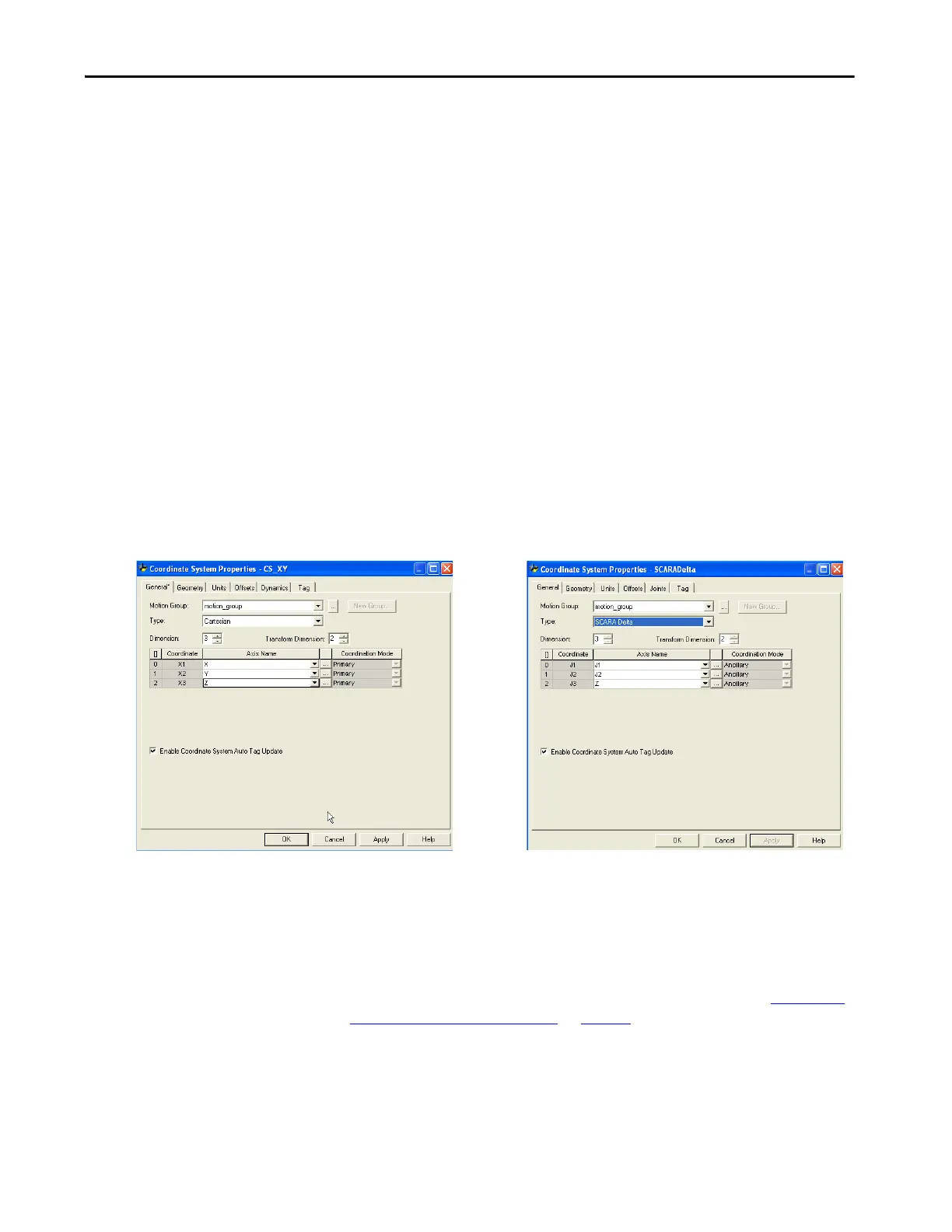
When configuring a SCARA Delta robot in Logix Designer application, keep
the following in mind.
•Configure both the source and the target coordinate system with a
transform dimension of two.
• The linear axis configured as a third axis must be the same for both the
source and target coordinate systems.
Figure 31 - Example of Source and Target Coordinate System Configuration for a SCARA Delta
Robot
Calibrate a SCARA Delta Robot
The method used to calibrate a SCARA Delta robot is the same as the method
used for calibrating a Delta three-dimensional robot. The only difference is the
number of axes used. For more information about calibration, see Calibrate a
Delta Three-dimensional Robot on page 64.

 Loading...


