96 Rockwell Automation Publication MOTION-UM002E-EN-P - June 2016
Chapter 5 Configure an Articulated Dependent Robot
Work Envelope
The work envelope is the three-dimensional region of space that defines the
reaching boundaries for the robot arm. The work envelope of an articulated
robot is ideally a complete sphere having an inner radius equal to |L1- L2| and
outer radius equal to |L1+L2|. However, due to the range of motion
limitations on individual joints, the work envelope is not always a complete
sphere.
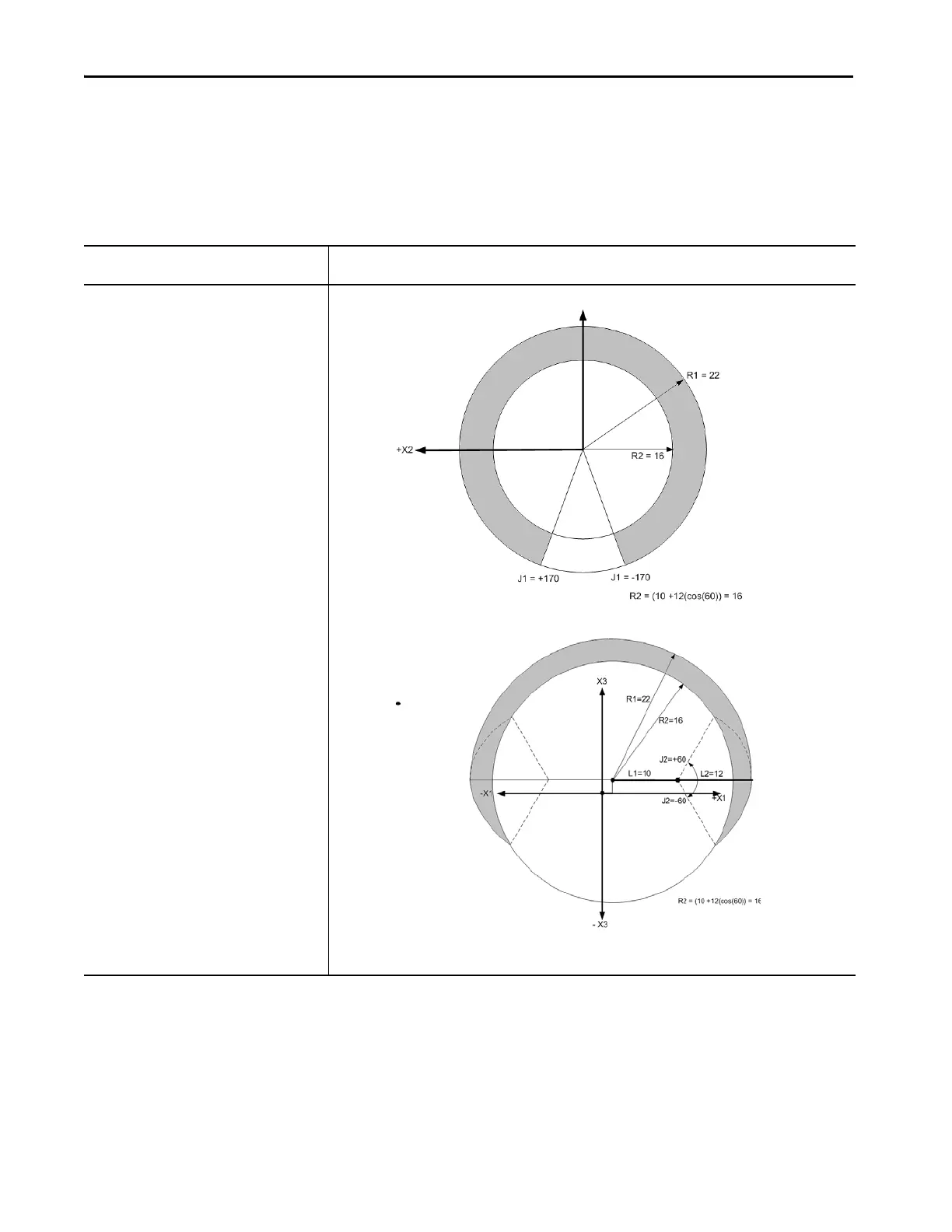
If the range-of-motion values for the
articulated robot are
Typically, the work envelope is
J1 = ± 170
J2 = 0...180
J3 = ± 60
L1 = 10
L2 = 12
Top view - Depicts the envelope of the tool center point sweep in J1 and J3 while J2 remains at a fixed position of 0.
Side view -
Depicts the envelope of the tool center point sweep in J2 and J3 while J1 remains at a fixed position of 0.

 Loading...


