Rockwell Automation Publication MOTION-UM002E-EN-P - June 2016 63
Configure an Articulated Independent Robot Chapter 4
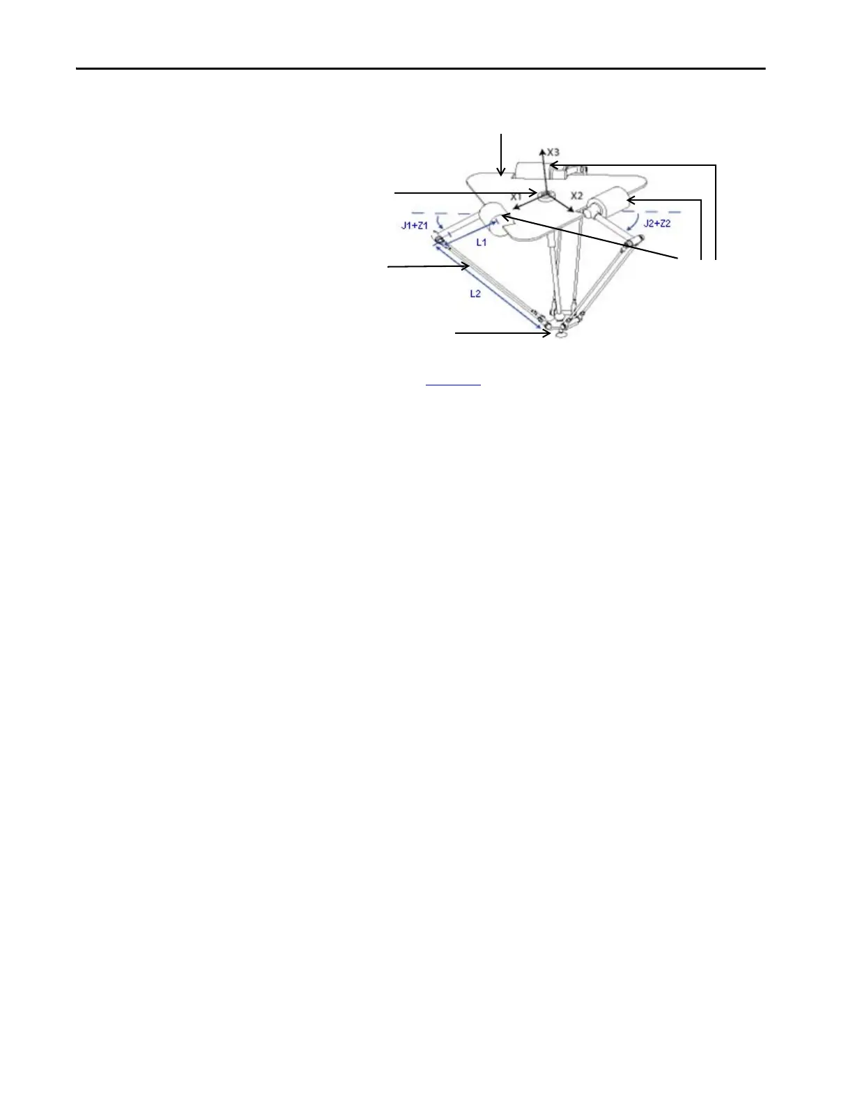
Figure 17 - Delta Three-dimensional Robot
The Delta robot in Figure 17 is a three-degree of freedom robot with an
optional fourth degree of freedom used to rotate a part at the tool tip. In
Logix Designer application, the first three-degrees of freedom are configured as
three joint axes (J1, J2, J3) in the robots coordinate system. The three joint
axes are either:
• directly programmed in joint space.
• automatically controlled by the embedded Kinematics software in Logix
Designer application from instructions programmed in a virtual
Cartesian coordinate system.
This robot contains a fixed top plate and a moving bottom plate. The fixed top
plate is attached to the moving bottom plate by three link-arm assemblies. All
three of the link-arm assemblies are identical in that they each have a single top
link arm (L1) and a parallelogram two-bar link assembly (L2).
As each axis (J1, J2, J3) is rotated, the TCP of the gripper moves
correspondingly in (X1, X2, X3) direction. The gripper remains vertical along
the X3 axis while its position is translated to (X1, X2, X3) space by the
mechanical action of the parallelograms in each of the three forearm
assemblies. The mechanical connections of the parallelograms via spherical
joints ensure that the top and bottom plates remain parallel to each other.
You program the TCP to an (X1, X2, X3) coordinate, then
Logix Designer application computes the commands necessary for each of the
joints (J1, J2, J3) to move the gripper linearly from the current (X1, X2, X3)
position to the programmed (X1, X2, X3) position, at the programmed vector
dynamics.
When each top link (L1) moves downward, its corresponding joint axis (J1, J2,
or J3) is assumed to be rotating in the positive direction. The three joint axes of
the robot are configured as linear axes.
To rotate the gripper, configure a fourth axis as either a linear or rotary,
independent axis.
Actuators for axes 1 - 3.
Baseplate
Forearm assembly
Gripper
Actuator for axis 4

 Loading...


