Rockwell Automation Publication MOTION-UM002E-EN-P - June 2016 75
Configure an Articulated Independent Robot Chapter 4
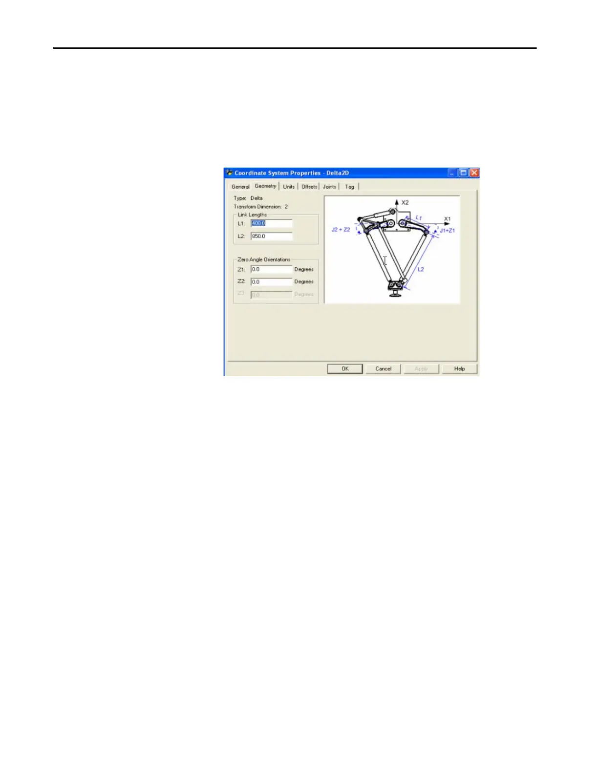
Link Lengths
Links are the rigid mechanical bodies attached at joints. The two- dimensional
Delta geometry has two link pairs, each with the same lengths. The link
attached to each actuated joint (J1 and J2) is L1. The parallel bar assembly
attached to link L1 is link L2.
Figure 28 - Two-dimensional Delta Robot - Link Lengths Configuration Screen
Base Offsets
There is one base offset (X1b) available for the two-dimensional Delta robot
geometry. Enter the value equal to the distance from the origin of the robot
coordinate system to one of the actuator joints.

 Loading...


