Publication 1794-6.5.8 - January 2010
126 Calibrating Your Module
Calibrating Voltage Outputs
Voltage calibration requires offset calibration followed by gain
calibration.
Offset Calibration for Voltage Outputs
Refer to the output timing diagram when calibrating the module.
Normally all outputs are calibrated together. To calibrate the offset of
an output, proceed as follows:
1. If you are not calibrating all channels with the same
configuration, select the channel to be calibrated by setting the
bit for that channel.
2. Send a block transfer write (BTW) to the module with individual
channel bits set for the configuration desired for each output.
This effectively terminates any previous configuration of the
module/channel.
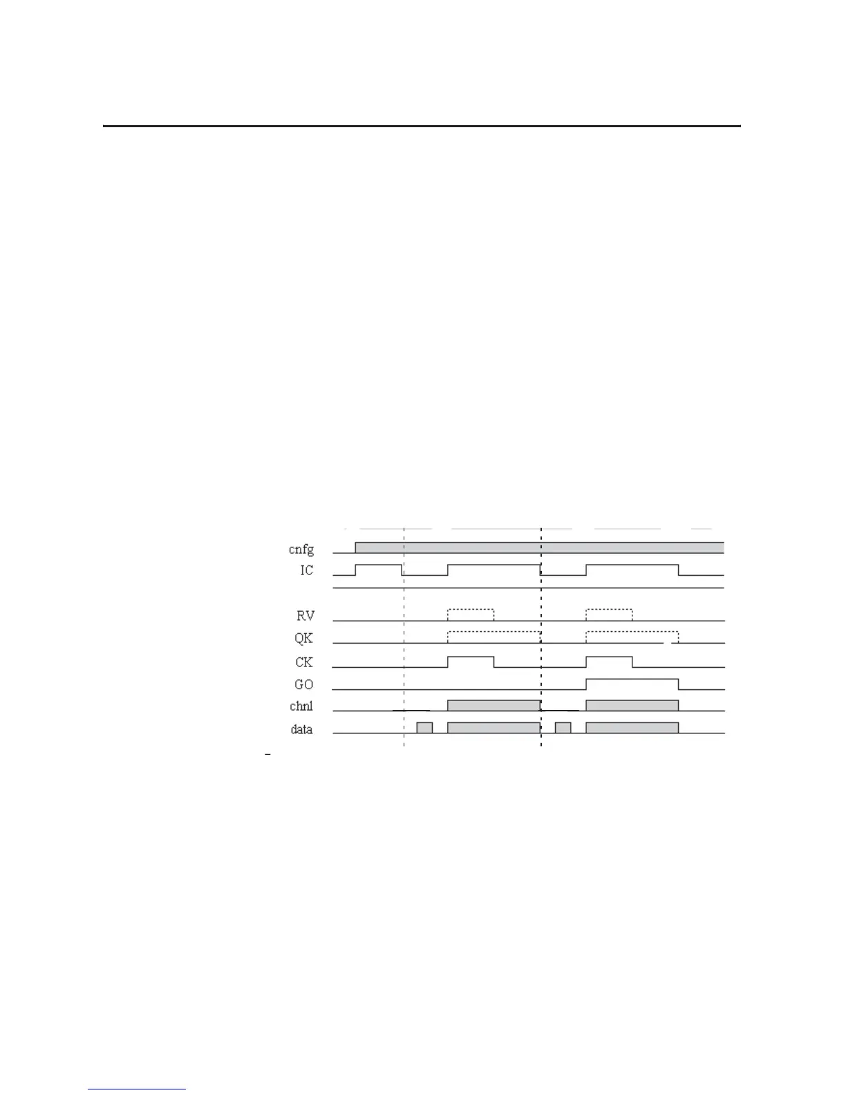
Figure 7.3
Output Calibration Timing Diagram
3. Clear all offset and gain coefficients by :
a. Set output data to 0 and the IC bit to 1
b. With GO = 0, toggle the CK bit
c. With GO = 1, toggle the CK bit
d. Clear the IC bit
Bit
15
Bit 14
Bit 07
Bit 06
Bit 05
Bit 04
Bit 01 ± 03
Configuration
Gain
Offset
1

 Loading...


