Publication 1794-6.5.8 - January 2010
132 Calibrating Your Module
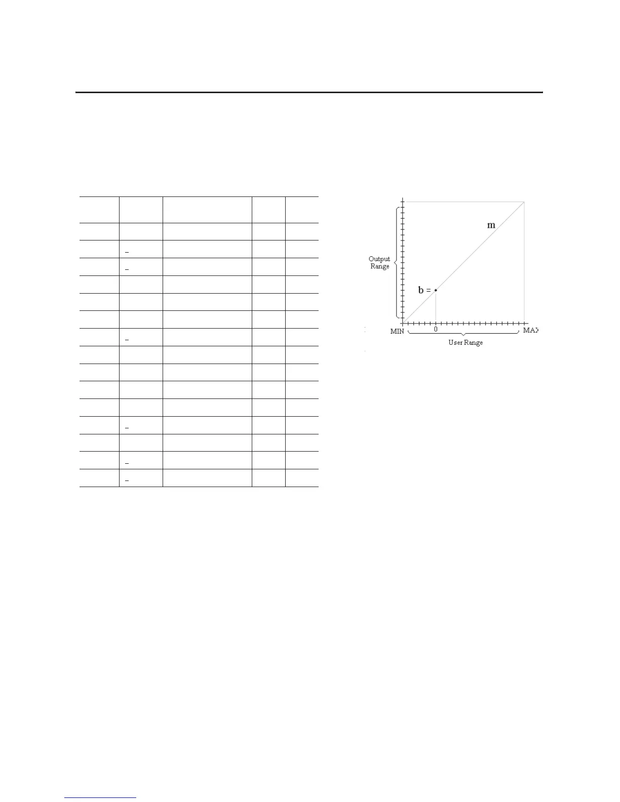
Scaling Outputs
Outputs are scaled in the same manner as the inputs and are
represented by the following illustration.
The gain, m, and offset, b, coefficients are calculated as follows:
m = Output Range / User Range
b = Z – mx
where: Z is the value, from the table, that sends a “zero” output*,
x0 is the user signal that is associated with “zero” output.
* in 4–20mA modes, “zero” is 4mA.
Chapter Summary
In this chapter, you learned how to calibrate your isolated analog
module.
Configu-
ration
Nominal
Range
Data Type Output
Range
Z
1 4–20mA signed 2’s complement 30840 0
2+
10V signed 2’s complement 62416 0
3+
5V signed 2’s complement 62416 0
4 0–20mA signed 2’s complement % 10000 0
5 4-20mA signed 2’s complement % 10000 0
6 0–10V signed 2’s complement % 10000 0
7+
10V signed 2’s complement % 20000 0
8 0–20mA binary 62415 0
9 4–20mA binary 61681 0
A 0–10V binary 62415 0
B 0–5V binary 62415 0
C+
20mA offset binary 31208 32768
D 4–20mA offset binary 30840 32768
E+
10V offset binary 62416 32768
F+
5V offset binary 62416 32768

 Loading...


