Publication 1794-6.5.8 - January 2010
26 How to Install Your Analog Module
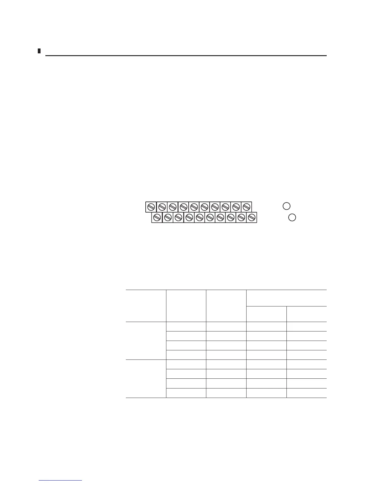
Wiring to a 1794-TBN or 1794-TBNF Terminal Base Unit
1. Connect individual input or output wiring to the even numbered
terminals on row (B) as indicated in the table below.
2. Connect the associated return wiring to the corresponding odd
numbered terminal on row (C) for each input or output as
indicated in the table below.
3. Connect 24V dc to terminal 34 on row (C).
4. Connect 24V dc common to terminal 16 on row (B).
5. If continuing power to the next terminal base unit, connect a
jumper from terminal 51 (24V dc) on this base unit to terminal
34 on the next base unit.
If continuing common to the next terminal base unit, connect a
jumper from terminal 33 (24V dc common) on this base unit to termi-
nal 16 on the next base unit.
0246810121433
16
13 57 9 11131551
34
16,
0, 2, 4, 6,
8, 10, 12, 14, 33
34, 1, 3, 5, 7,
9, 11, 13, 15, 51
C
B
1794-TBN, 1794-TBNF
16 33Even
Numbered T
erminals 0 thru 14
34 51
Odd Numbered Terminals 1 thru 15
Table 2.1
Wiring connections for 1794-TB3, -TB3T, -TB3S, -TB3TS, -TBN and -TBNF Terminal Base
Units when using the 1794-IF4I or 1794-OF4I Isolated Analog Module
Channel Signal Type Label Markings
1794-TB3, -TB3T1, -TB3S, -TB3TS
(2)
1794-TBN, 1794-TBNF
Signal
Terminal
Signal Return
0 Current I0 0
Current I0 Ret 1
Voltage V0 2
Voltage V0 Ret 3
1 Current I1 4
Current I1 Ret 5
Voltage V1 6
Voltage V1 Ret 7

 Loading...


