Publication 1794-6.5.8 - January 2010
32 Module Programming
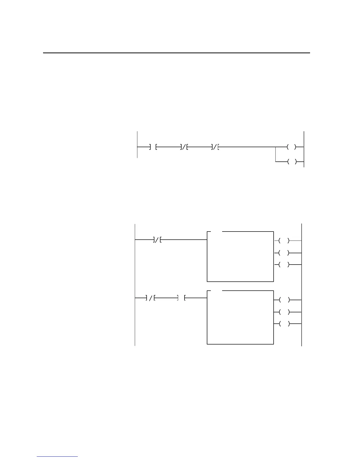
Configuration Rungs
Example Configuration Rungs
It is necessary to toggle the IC bit
(1)
(initiate configuration) for the
isolated analog modules to accept configuration data. Once the
configuration data has been properly set up, the following rung will
reconfigure the module (this example represents sizes for the
1794-IF4I module).
If there are rungs which already perform reads and writes to the
module, no additional rungs are necessary. A simplified example of a
BTR and BTW rung for an 1794-IF4I follow (the 1794-OF4I is read
length 6, write length 7; the 1794-IF2XOF2I is read length 7, write
length 7):
An XIC ( ––] [–– ) instruction of the Power Up bit (PU) can be inserted
to allow BTWs only when the module requires configuration (PU = 1).
(1)
For systems that do not require ladder program control of configuration, set the TR bit (bit 13) to 1. Refer to
Chapter 1.
2
14
B12:15
15
13
Power-up Bit
FP Bit
CF Bit
15
IC Bit
B12:15 B12:15 B12:54
L
B12:54
14
BTR Enable Bit
EN
DN
BTW Enable Bit
1
3
ER
EN
DN
ER
BTR
BLOCK
TRANSFER READ
RACK:
GROUP:
MODULE:
DATA FILE:
LENGTH:
CONTINUOUS: N
BTW
BLOCK
TRANSFER WRITE
RACK:
GROUP:
MODULE:
LENGTH:
CONTINUOUS: N
01
0
0
N12:10
7
01
0
0
5
CONTROL:
N13:10
DATA FILE:
N12:50
CONTROL:
N13:0
N3:0
15
N13:10
15
PU Bit
N12:15
15
Optional

 Loading...


