Publication 1794-6.5.8 - January 2010
56 Writing Configuration to and Reading Status from Your Module with a Remote I/O Adapter
The real time sample interval can be set from 0 to 30s, in increments
of 5ms. Set the real time sample interval in binary using 15 bits in the
block transfer write word.
The individual channel update times determines how fast you can get
new information collectively from the module. The module gathers
the data from each input and makes it available to the processor. For
example, if channel 0 is 2.5ms, channel 1 is 5.0ms, and channel 2 is
7.5ms, and RTS = 0, each channel will be updated at its stated rate. If
RTS is set to 5ms, only channels 0 and 1 are fast enough to be
included in the real time sample. In order to include channel 2 in your
synchronous sample, you must set the RTS to 10ms minimum. Your
updated information will be accurate for all inputs/outputs as viewed
at the last update before the time of your request.
Input Filtering
The input modules have selectable input filtering built into the A/D
converter. The filter attenuates the input signal beginning at the speci-
fied frequency. You can select from 150, 300, 600, and 1200Hz with
low pass filters of none, 100ms, 500ms or 1000ms. Each channel filter
Word/Dec. Bit 15 14 13 12 11 10 09 08 07 06 05 04 03 02 01 00
Word/Octal Bit 17 16 15 14 13 12 11 10 07 06 05 04 03 02 01 00
Word 3 0 Real Time Sample Programmed Interval
ATTENTION
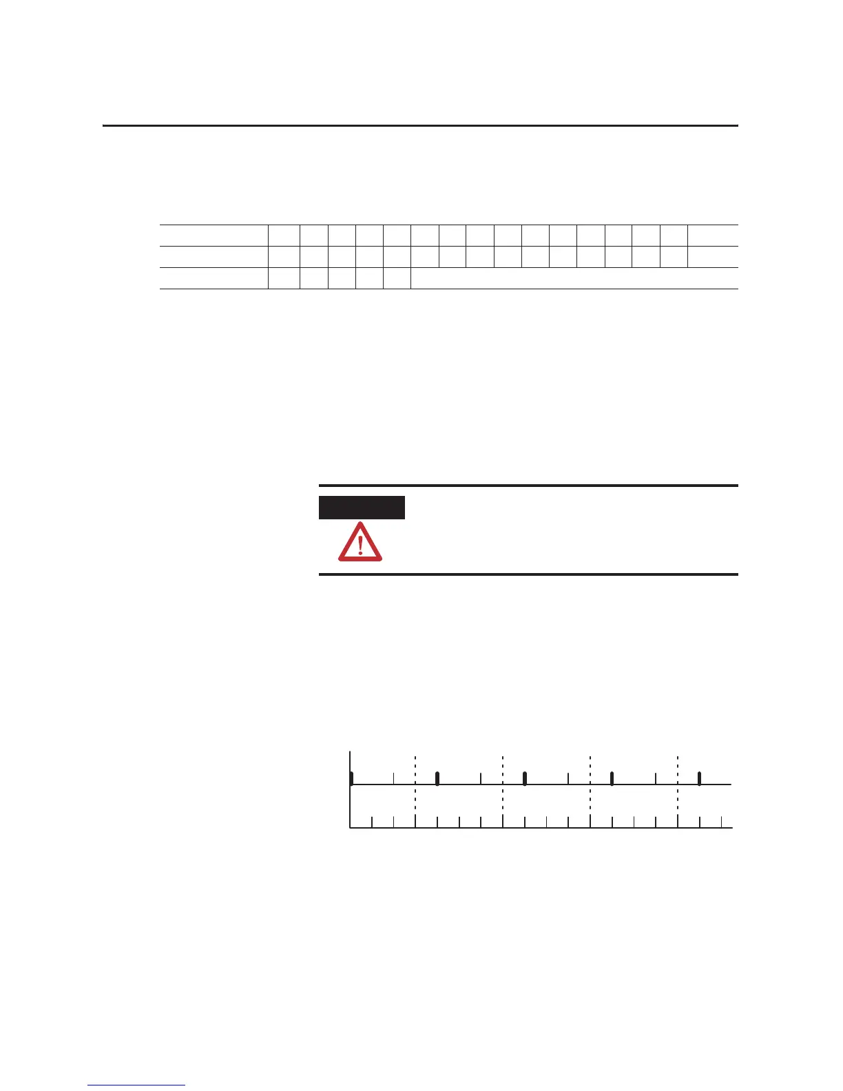
Do not set your real time sample interval less than
the slowest channel’s update time.
Slowest
Channel Update T
ime= 7.5ms
Internal R
TS Timer = 10ms
5101520 307.5 27.5 37.53525 40
4 inputs and R
TS updated
10 20 30 40
4 inputs and R
TS updated
4 inputs and R
TS updated
4 inputs and R
TS updated
0
0
17.5

 Loading...


