Publication 1794-6.5.8 - January 2010
64 Writing Configuration to and Reading Status from Your Module with a Remote I/O Adapter
4 Isolated Output Analog Module (Cat. No. 1794-OF4I)
Module
Image
I/O Image
Read Back Channel 0
Read Back Channel 1
Read Back Channel 2
Read Back Channel 3
Input Size
Output Size
2 to 7 Word
0 to 6 Words
PU FP CF BD DN
Channel Configuration
IC RV QK CK GO
Channel #
Set to 0EN
Hold
Outputs
Wire-off
S1 S0
Output Data Channel 0
Output Data Channel 1
Output Data Channel 2
Output Data Channel 3
1 Q3 Q2 Q1 Q0TR IT
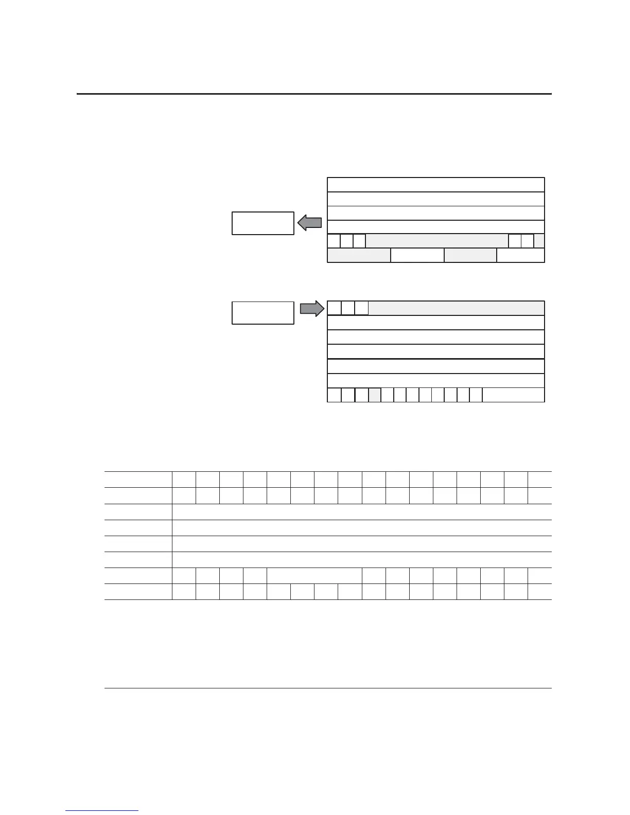
Table 4.9
Analog Output Module (1794-OF4I) Read
Word/Dec. Bit 15 14 13 12 11 10 09 08 07 06 05 04 03 02 01 00
Word/Octal Bit 17 16 15 14 13 12 11 10 07 06 05 04 03 02 01 00
Read Word 0 Read Back Channel 0
Word 1 Read Back Channel 1
Word 2 Read Back Channel 2
Word 3 Read Back Channel 3
Word 4 PU FP CF 0 Reserved 00000BDDN0
Word 5 0000P3P2P1P00000W3W2W1W0
Where:
PU = Power up unconfigured state
FP = Field power off
CF = In configuration mode
BD = Calibration bad
DN = Calibration accepted
P0 thru P3 = Output holding in response to Q0 thru Q3
W0 thru W3 = Wire off current loop status for channels 0 thru 3 respectively. (Not used on voltage outputs.)

 Loading...


