Publication 1794-6.5.8 - January 2010
38 Module Programming
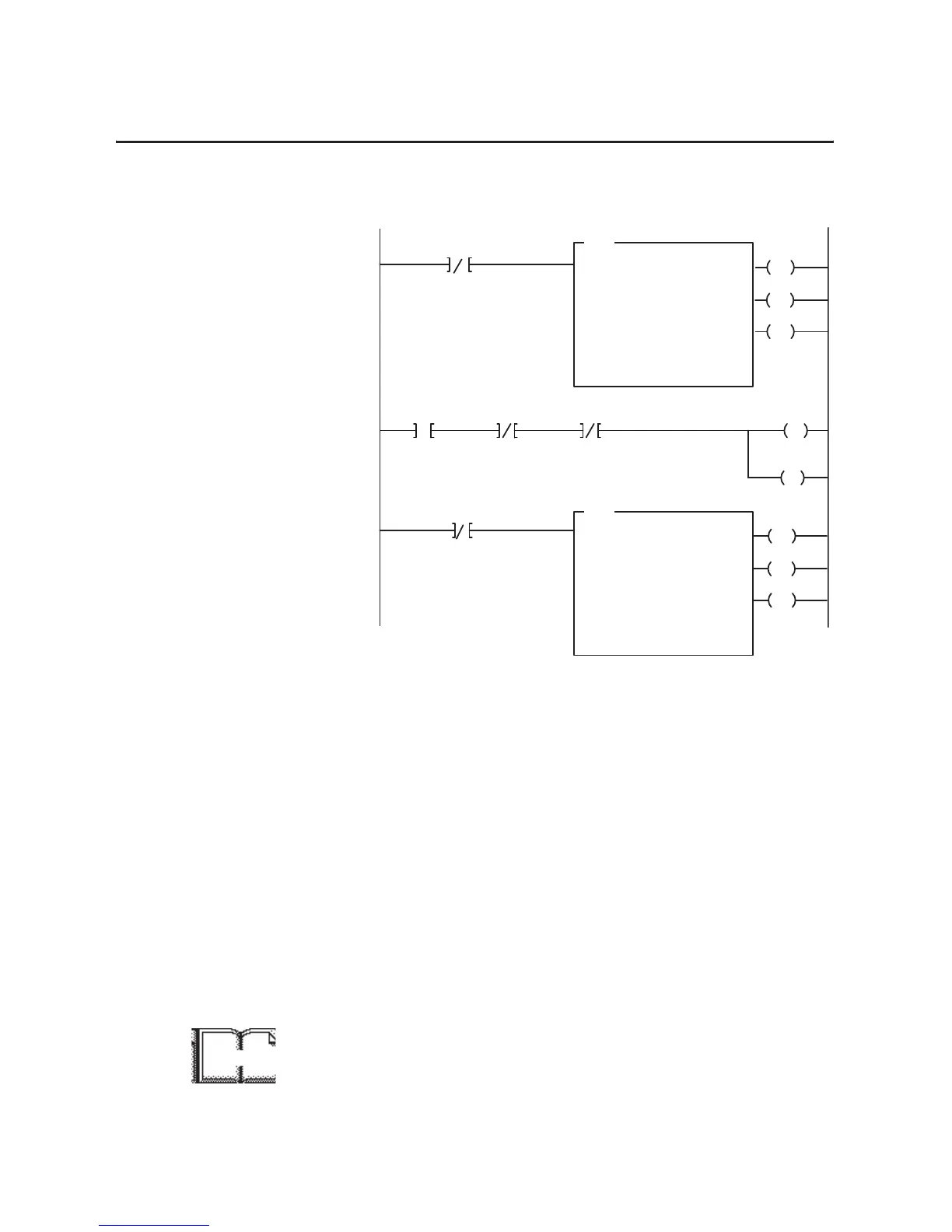
Figure 1.6
PLC-5 Family Sample Program Structure for the 1794-IF2XOF2I
PLC-2 Programming
The 1794 analog I/O modules are not recommended for use with
PLC-2 family programmable controllers due to the number of digits
needed for high resolution.
SLC-5 Programming
The SLC-5 programs (using the 1747-SN scanner) follow the same
logic as the PLC-5 family programs in the previous examples.
Differences occur in the implementation of block transfers due to the
use of “M” files in the SLC system.
Configuration data for the FLEX I/O isolated analog modules and the
1747-SN scanner must be in place before executing the following
programs. Chapter 4 contains information on the isolated analog
module configurations.
For more information on using the 1747-SN scanner module and
block transfer programming, refer to publication 1747-6.6, “Remote
I/O Scanner User Manual.”
BTR Enable Bit
EN
DN
BTW Enable Bit
1
3
ER
EN
DN
ER
BTR
BLOCK
TRANSFER READ
RACK:
GROUP:
MODULE:
DATA FILE:
LENGTH:
CONTINUOUS: N
BTW
BLOCK
TRANSFER WRITE
RACK:
GROUP:
MODULE:
LENGTH:
CONTINUOUS: N
2
3
0
N16:10
7
2
3
0
7
Program
Action
CONTROL:
N17:10
DATA FILE:
N16:50
CONTROL:
N17:0
N17:0
15
N17:10
15
Thereafter, the program continuously
performs read block transfers and write block
transfers.
2
14
N16:15
15
13
Power-up Bit
FP Bit
CF Bit
15
IC Bit
N16:56N16:15 N16:15
Then it initiates a block transfer write to
configure the module and send data
values.
This rung toggles the Initate Configuration
bit from 0 to 1 to 0
At power-up in RUN mode, or when the
processor is switched from PROG to RUN,
the user program enables a block transfer
read.
L
14
N16:56
THIS BIT
MUST
BE 1
More

 Loading...


