Publication 1794-6.5.8 - January 2010
How to Install Your Analog Module 23
6. Repeat the above steps to install the next module in its terminal
base unit.
Connecting Wiring for the
Analog Modules
Wiring to the analog modules is made through the terminal base unit
on which the module mounts.
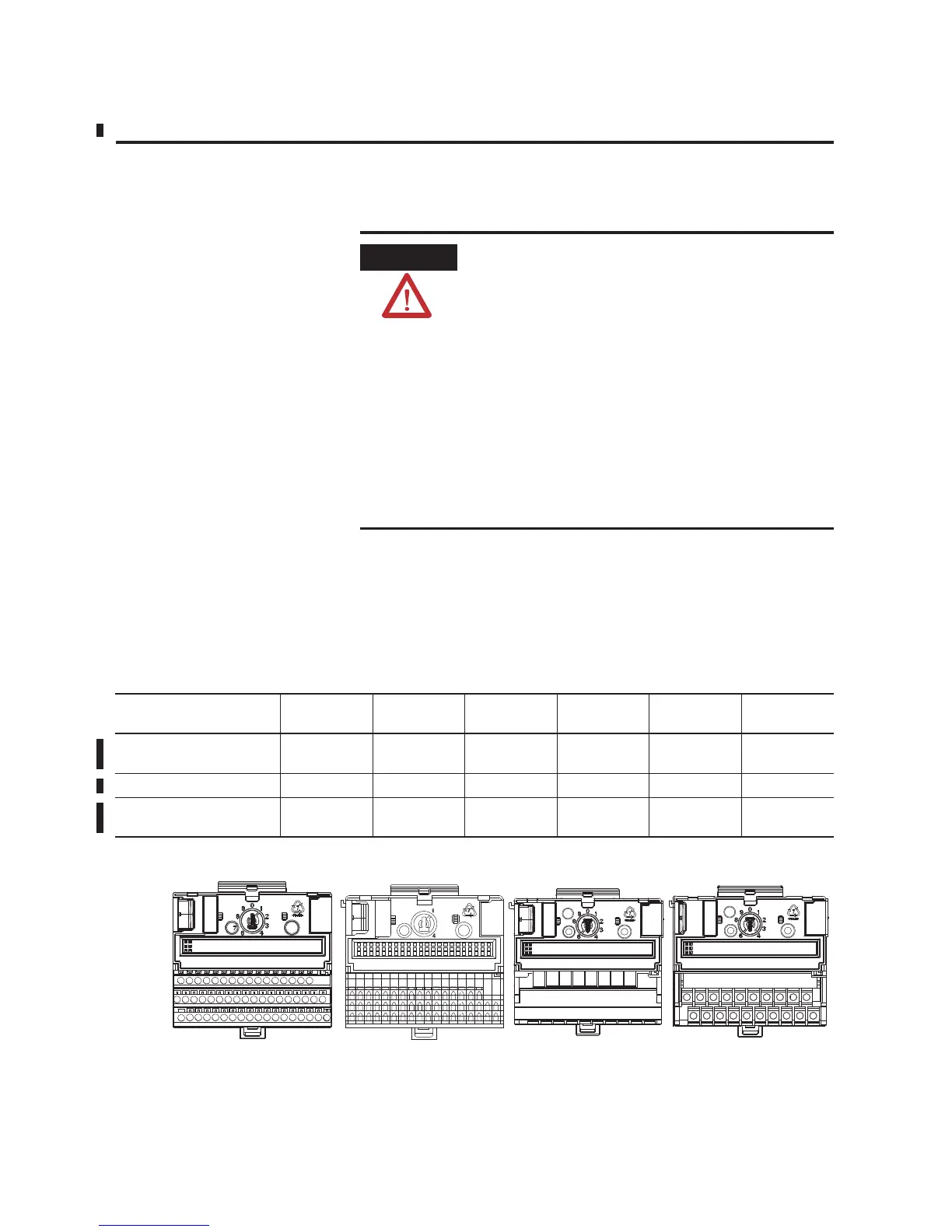
Refer to the following table for recommended terminal base units that
you can use for each module.
Figure 2.5
ATTENTION
Remove field-side power before removing or
inserting the module. This module is designed so
you can remove and insert it under backplane
power. When you remove or insert a module with
field-side power applied, an electrical arc may occur.
An electrical arc can cause personal injury or
property damage by:
• sending an erroneous signal to your system’s field
devices causing unintended machine motion
• causing an explosion in a hazardous environment
Repeated electrical arcing causes excessive wear to
contacts on both the module and its mating
connector. Worn contacts may create electrical
resistance.
Module 1794-TB3 1794-TBT 1794-TB3S 1794-TB3TS 1794-TB3S 1794-TBN,
-TBNF
1794-IF4I, 1794-IF4IXT,
1794-IF4ICFXT
Yes Yes Yes Yes Yes Yes
1794-OF4I, 1794-OF4IXT Yes Yes Yes Yes Yes Yes
1794-IF2XOF2I,
1794-IF2XOF2IXT
Yes Yes Yes Yes Yes Yes
1794-TB3, -TB3T 1794-TB3S, -TB3TS 1794-TBNF 1794-TBN

 Loading...


