Publication 1794-6.5.8 - January 2010
How to Install Your Analog Module 25
4. If daisy chaining the +24V dc power to the next base unit,
connect a jumper from terminal 51 on this base unit to terminal
34 on the next base unit. Connect the 24V dc common/return
from terminal 33 on this base unit to terminal 16 on the next
base unit.
ATTENTION
Remove field-side power before removing or
inserting the module. This module is designed so
you can remove and insert it under backplane
power. When you remove or insert a module with
field-side power applied, an electrical arc may occur.
An electrical arc can cause personal injury or
property damage by:
• sending an erroneous signal to your system’s field
devices causing unintended machine motion
• causing an explosion in a hazardous environment
Repeated electrical arcing causes excessive wear to
contacts on both the module and its mating
connector. Worn contacts may create electrical
resistance.
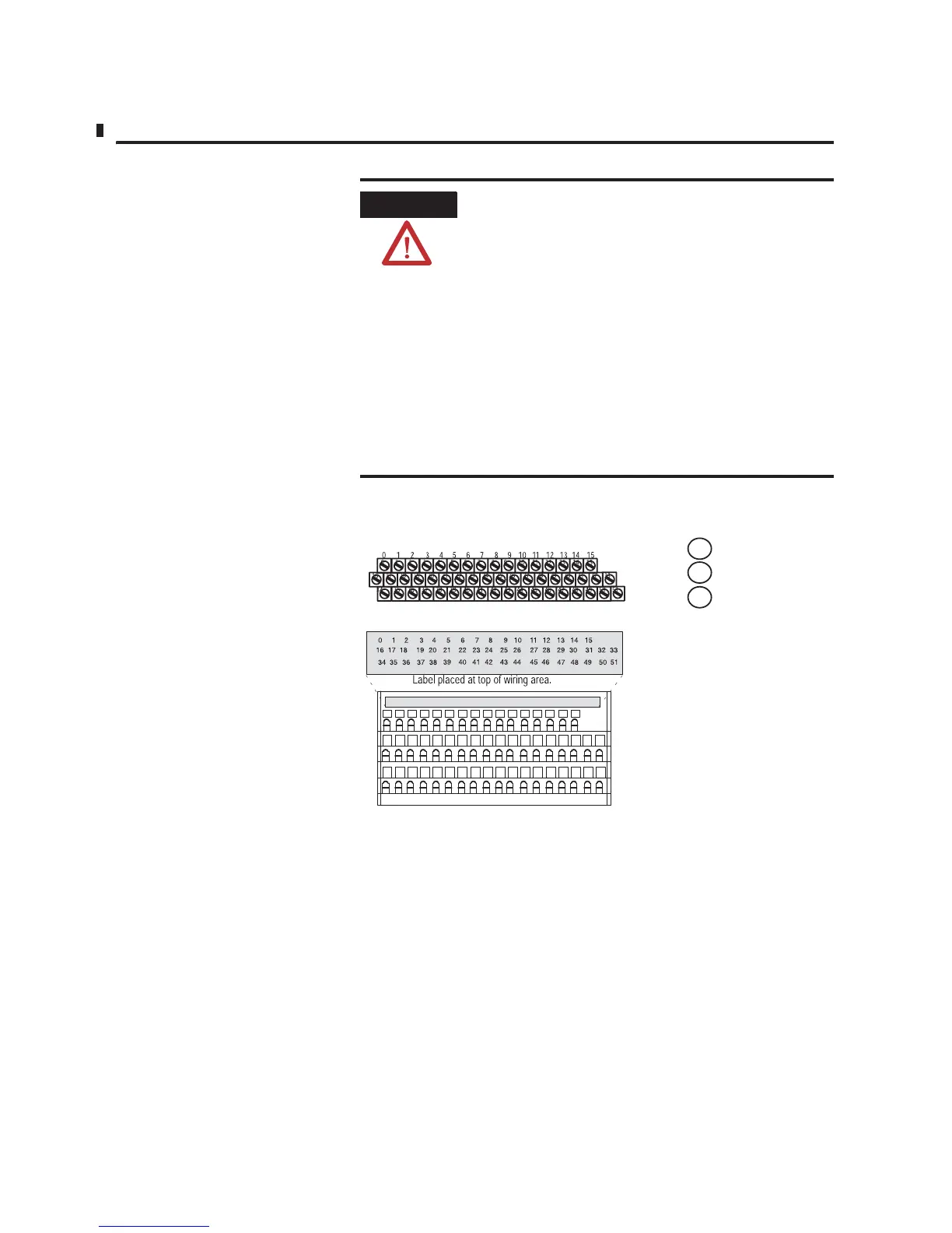
1794-TB3, -TB3T
0
±15
34±51
16±33
A
B
C
Row A
Row B
Row C
Row A
Row B
Row C
1794-TB3S, -TB3TS

 Loading...


