126 Rockwell Automation Publication 5000-UM005B-EN-P - November 2015
Appendix A Troubleshoot Your Module
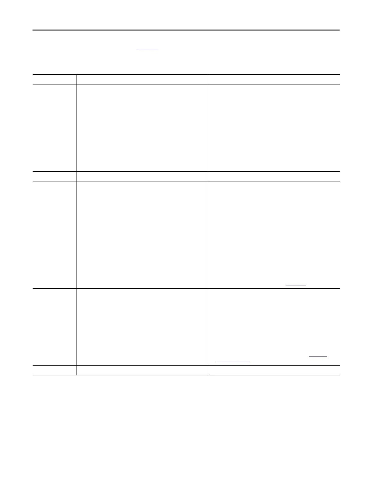
Table 28 describes the I/O Status indicator on 5069 Compact I/O analog
input modules.
Table 28 - I/O Status Indicator- 5069 Compact I/O Analog Input Modules
Indicator State Description Recommended Action
Off One of the following conditions exists:
• The module is not powered.
• The module is powered but no connection from the controller to module
has been established.
• The module is powered, but the input channel is disabled.
Complete one of the following:
• None - If your application does not use the input channel.
• If you expect the module to be powered but it is not, complete
the following:
– Confirm that the system is powered.
– Confirm that the module is installed properly.
• If the module is powered but the channel is not operating as expected,
use the Logix Designer application to confirm that the channel is not
disabled and has a connection to the controller.
The Connection category in the Module Properties for the module
indicates if the module is running or faulted. If the module is faulted, the
Connection category indicates error information affecting the state of
the module.
Steady yellow The input channel is operating normally. None
Steady red An issue has occurred that is internal to the module. The following are
example issues that can cause the status indicator to be steady red:
• The module has experienced a non-recoverable fault.
• A calibration fault occurred on the channel.
• The module is operating over its specified temperature. That is, an Over
Temperature condition exists.
Complete one of the following:
• If the indicator is in the steady red state following the initial power-up
sequence and remains in that state, replace the module.
• If a calibration fault occurred, cycle power to the module. When the
power-up sequence completes, the channel returns to the factory
calibration setting.
If the indicator remains in the steady red state after you cycle power,
replace the module.
• To return the module to the specified operating temperature range,
complete the following:
– Check the temperature at the module installation location and lower
it if necessary.
– Make sure the proper level of current is applied to the module. If not,
change the current applied to an acceptable level.
Module specifications, for example, acceptable operating temperature or
applied current levels, are available in the 5069 Compact I/O Modules
Specifications Technical Data, publication
5069-TD001.
Flashing red An external device caused a fault on the input channel. The following are
examples of issues that can cause the fault:
• The input signal is overrange or underrange.
The signal range is set in your Logix Designer application project.
• An Open Wire condition, that is, a wire is disconnected from the input
channel.
• The module is using SA bus power but the power is not available
or correct.
Complete one of the following:
• Check the input signal to determine if it is overrange or underrange.
If so, make changes to return the input signal to within the range limits.
• Check the wiring at the input channel.
If necessary, reconnect the wire.
• Check the SA connector, available on a 5069-AEN2TR adapter or a
5069-FPD module to make sure 24 V DC power is present.
If 24 V DC power is not present, troubleshoot the SA power connection.
For more information on using the SA connector, see the 5069-AEN2TR
adapter and 5069-FPD module documentation listed in
Additional
Resources on page 7.
Alternating yellow/red Calibration is in progress. Finish the calibration process in the Logix Designer application.

 Loading...
