46 Rockwell Automation Publication 5000-UM005B-EN-P - November 2015
Chapter 3 Current/Voltage Analog Input Module Features (5069-IF8)
Alarm Deadband
You can configure an alarm deadband to work with these alarms. The deadband
lets the process alarm status bit remain set, despite the alarm condition
disappearing, as long as the input data remains within the deadband of the
process alarm.
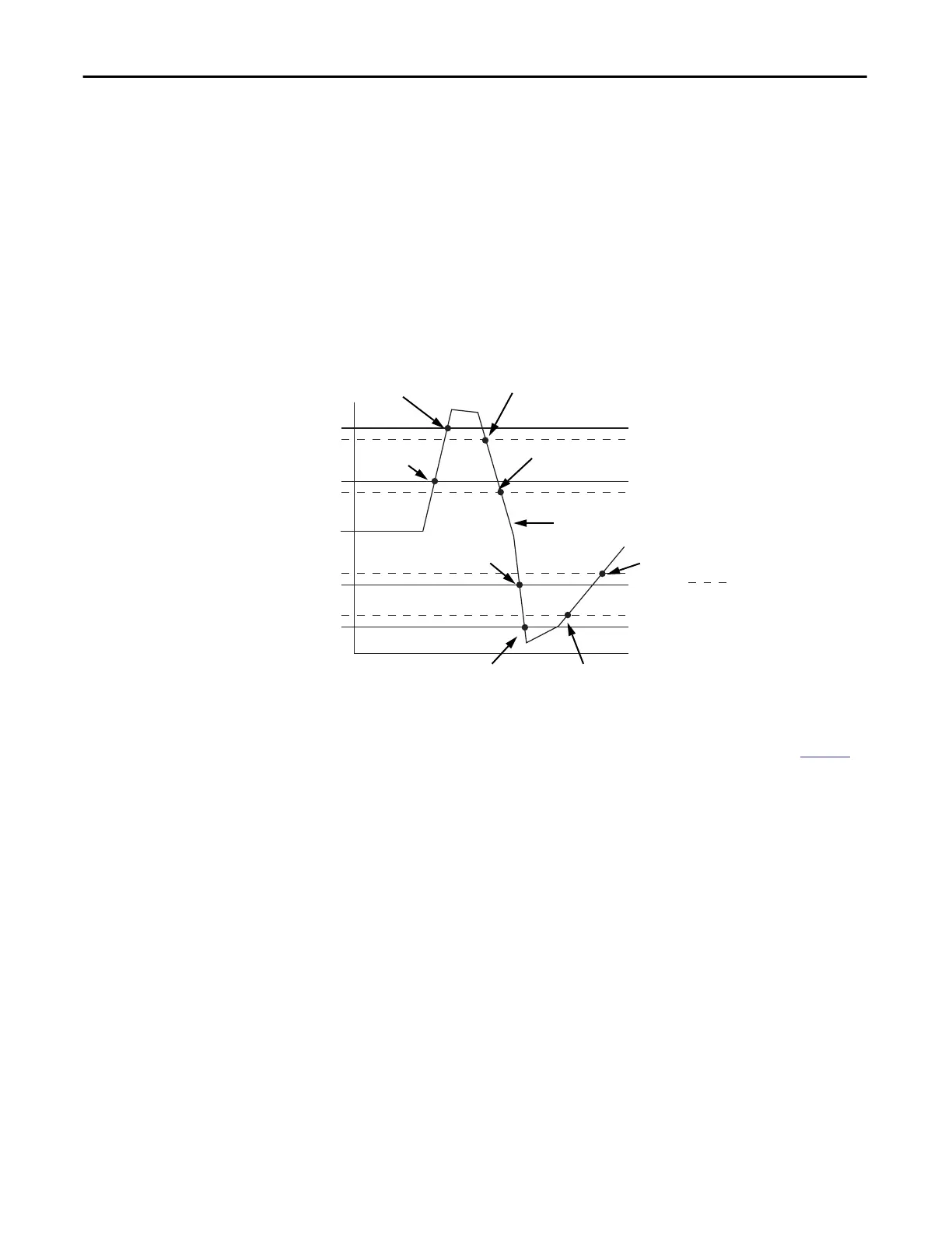
The following graphic shows input data that sets each of the four alarms at some
point during module operation. In this example, latching is disabled; therefore,
each alarm turns Off when the condition that caused it to set ceases to exist.
Figure 5 - Alarm Deadband Alarm Settings
To see where to set the Alarm Deadband on the 5069-IF8 module, see page 93.
43153
High high
Low low
Low
High
Alarm Deadbands
High high alarm turns Off.
High alarm remains On.
High high alarm turns On.
High alarm remains On.
Normal Input Range
Low low alarm turns Off.
Low alarm remains On.
High alarm turns Off.
Low low alarm turns On.
Low alarm remains On.
Low alarm turns Off.Low alarm turns On.
High alarm
turns On.

 Loading...
