134 Rockwell Automation Publication 825-UM004D-EN-P - November 2012
Chapter 10 Modbus RTU Communications
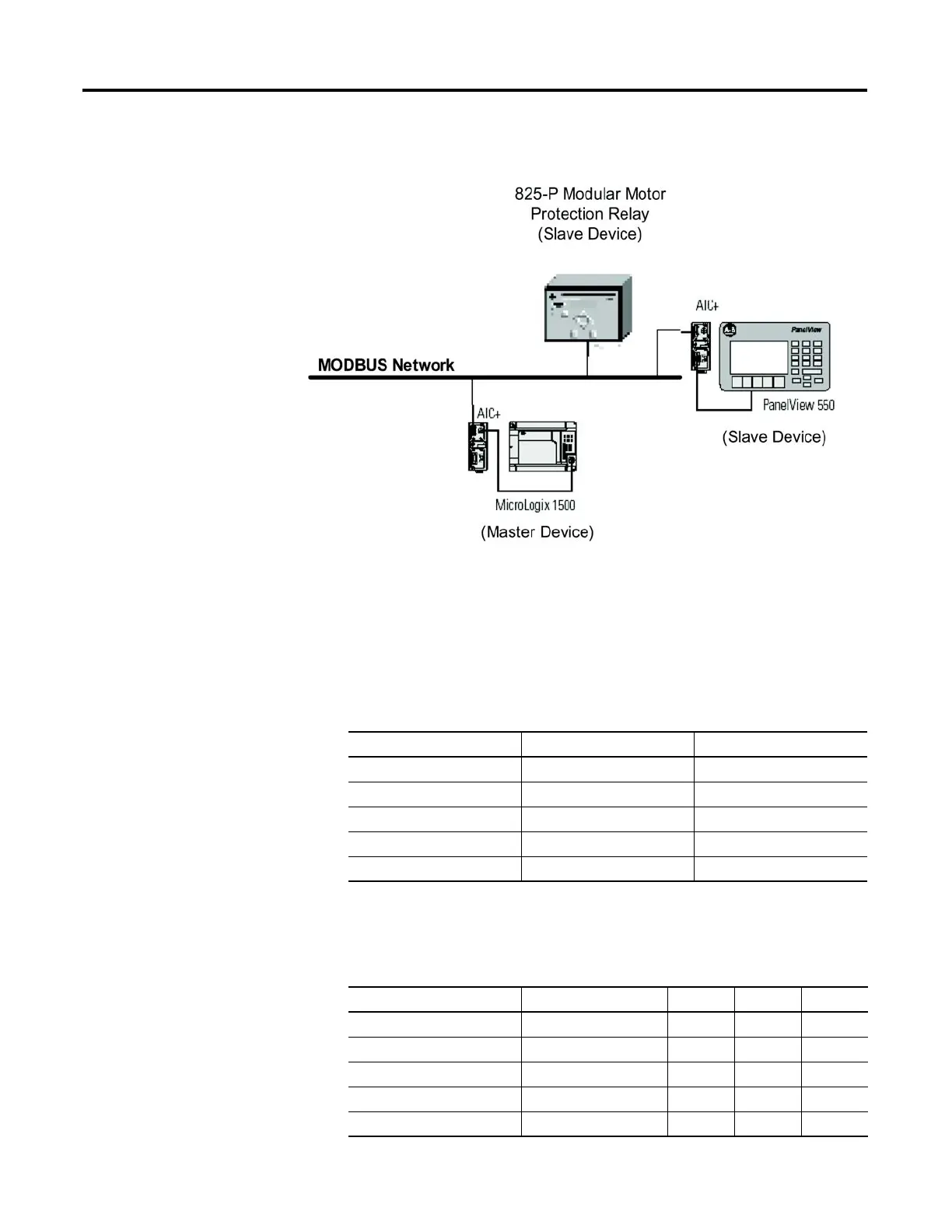
Figure 47 - Example of Modbus network consisting of a MicroLogix 1500 PLC as the Master device
and an 825-P and PanelView 550 as the Slave devices.
Commissioning
The Modbus communication card (Port 4) can be configured through
the front panel or serial port using the following settings. Front panel
access uses the following path:
MAIN > Set/Show > Port > Port 4
Table 63 - Modbus communication card settings
The following table provides settings to use for each communication card:
Table 64 - Communication card settings
Setting Prompt Setting Range Factory Default
COMM INTERFACE 232, 485 232
PROTOCOL ASC, MOD MOD
SPEED 300 … 38,400 bps 19,200
PARITY O, E, N N
MODBUS SLAVE ID 1 … 248 248
Setting Prompt Setting Range DeviceNet Modbus Empty
COMM INTERFACE 232, 485 232 232 232
PROTOCOL ASC, MOD MOD MOD MOD
SPEED 300 … 38,400 bps 19,200 19,200 19,200
PARITY O, E, N NNN
MODBUS SLAVE ID 1 … 248 248 1 to 247 1

 Loading...