Rockwell Automation Publication 825-UM004D-EN-P - November 2012 21
Installation Chapter 2
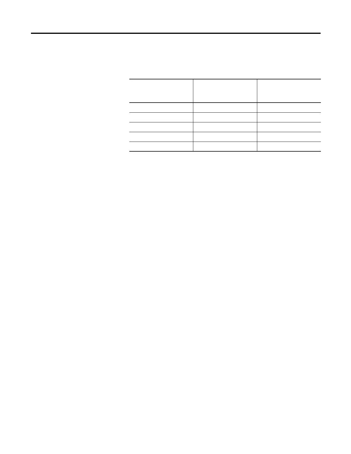
Table 2 shows the maximum cable lengths for the PTC connections.
Table 2 - PTC Cable Requirements
AC/Control Connection
Diagrams
This section describes fail-safe versus non-fail-safe tripping, describes voltage
connections, and provides the AC and DC wiring diagrams for the following
applications:
• Across the line starting
• Star-delta starting
• Two -spe ed motor
Fail-Safe/Non-Fail-Safe Tripping
The Trip relay can be configured for Fail-Safe or Non-Fail-Safe operation by way
of the Relay Behavior settings group discussed in Output Relay Behavior on
page92. The Trip relay output is a Form C contact consisting of a common
terminal, a normally open (N.O.) terminal and a normally closed (N.C.)
terminal. The terminals require different contact designations based on whether
the Trip relay is configured for Fail-Safe or Non-Fail-Safe operation.
The proper contact designations for Fail-Safe and Non-Fail-Safe configurations
are identified in Figure 6. Be certain to apply the appropriate marking strip to the
terminal plug corresponding to the configuration of the relay's trip output.
The 825-P provides fail-safe and non-fail-safe trip modes (setting selectable) for
the Trip and Aux (auxiliary) contacts. The following occurs in fail-safe mode:
• The Trip relay coil is energized continuously.
• When the 825-P generates a trip signal, the Trip relay coil is de-energized.
• The Trip relay coil is also de-energized if the 825-P input power is removed
or if t
h
e 825-P fails (self-test status is FAIL).
Wire Size,
Twisted Pair,
AWG No.
Maximum Length
(meters) Shielded Cable
Maximum Length
(meters)
Unshielded Cable
20 200 100
18 300 100
17 400 100
16 600 100
14 1000 100

 Loading...