22 Rockwell Automation Publication 825-UM004D-EN-P - November 2012
Chapter 2 Installation
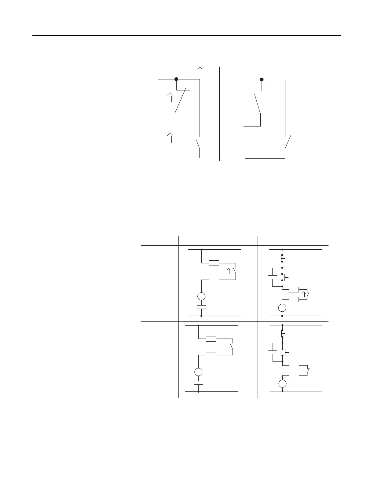
Figure 6 - TRIP Relay Output Contact Configurations
Figure 7 shows fail-safe and non-fail-safe wiring methods to control breakers and
contactors. Keep in mind that the “Fail-Safe (Electrically Held)” and “Non-Fail-
Safe” labels apply to the whole row that they are aligned with and not just to the
single diagram that they are next to.
Figure 7 - TRIP Contact Fail-Safe and Non-Fail-Safe Options
NOTE: Contact numbering changes are based on TRIP Fail-Safe setting.
Fail-Safe Tripping ( )
Non-Fail-Safe Tripping
95
96
98
TRIP
95
98
96
TRIP
NOTE: Contact numbering changes are based on the TRIP Fail-Safe Setting.
Fail-Safe
(Electrically Held)
Non-Fail-Safe
Circuit Breaker
Contactor
CR
96
95
STOP
START
Contactor Coil
CR
52A
Breaker Trip Coil
TC
98
95
CR
STOP
START
96
95
Contactor Coil
CR
95
TC
52A
Breaker Trip Coil
98

 Loading...