Rockwell Automation Publication 825-UM004D-EN-P - November 2012 137
Modbus RTU Communications Chapter 10
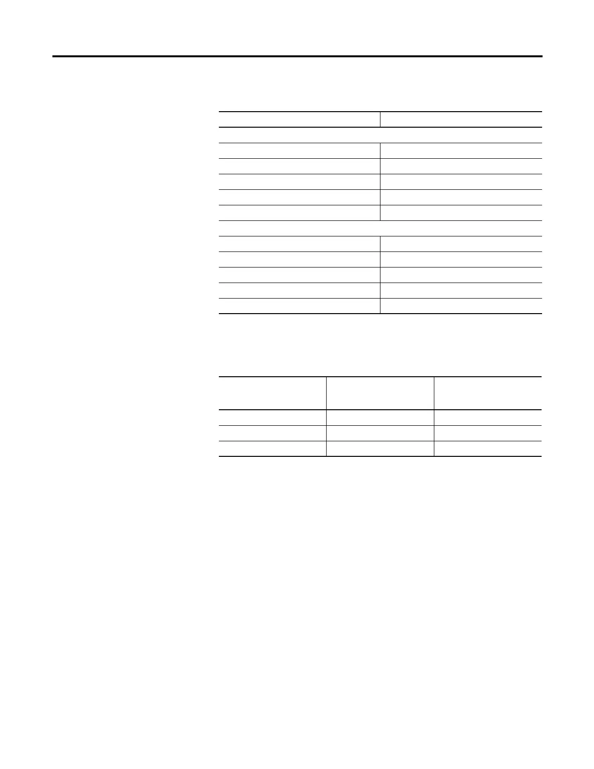
Table 68 - 03h Read Holding Register Command (Sheet 1 of 2)
The relay responses to errors in the query are shown in Table 69.
Table 69 - Responses to 03h Read Holding Register Query Errors
06h Preset Single
Register Command
The 825-P uses this function to allow a Modbus master to write directly to a
database register. Refer to the Modbus Register Map in Appendix B for a list
of registers that can be written using this function code. If you are accustomed
to 4X references with this function code, for six-digit addressing, add 400001
to the standard database addresses.
In Table 70, the command response is identical to the command request.
Bytes Field
Requests from the master must have the following format:
1 byte Slave Address
1 byte Function Code (03h)
2 bytes Starting Register Address
2 bytes Number of Registers to Read
2 bytes CRC-16
A successful response from the slave will have the following format:
1 byte Slave Address
1 byte Function Code (03h)
1 byte Bytes of data (n)
n bytes Data (2…250)
2 bytes CRC-16
Error Error Code Returned Communication
Counter
Increments
Illegal register to read Illegal Data Address (02h) Invalid Address
Illegal number of registers to read Illegal Data Value (03h) Illegal Register
Format error Illegal Data Value (03h) Bad Packet Format
The first holding register (parameter) for the 825-P ia 1. Some Modbus masters
use 0 as the first holding register. This can give the appearance of data being
offset by one register.

 Loading...