78 Rockwell Automation Publication 825-UM004D-EN-P - November 2012
Chapter 6 Configuring Protection & Logic Functions
Current Imbalance/
Phase Loss
Imbalanced motor terminal voltages cause imbalanced stator currents to flow in
the motor. The negative-sequence current component of the imbalance current
causes significant rotor heating. While the 825-P motor thermal element models
the heating effect of the negative-sequence current, you could want the additional
imbalance and single-phasing protection offered by a current imbalance element.
The 825-P calculates percent imbalance current in one of two ways, depending
on the magnitude of the average current.
When the average current, Iav, is:
1. greater than the motor-rated full load current, the relay calculates the
percent imbalance:
2. less than the moto
r-rated full load current, the relay calculates the percent
imbalance:
where:
U
B%
= current imbalance percentage
Im = magnitude of phase current with largest deviation from average
Iav = magnitude of the average phase current
FLA = motor-rated full load current
In either case, the function is disabled if the average phase current magnitude is
less than 25% of the Full Load Amps setting.
A 1% voltage imbalance typically causes approximately 6% current imbalance in
induction motors. If a 2% voltage imbalance can occur in your location, set the
current imbalance Warn Level greater than 12% to prevent nuisance alarms. A
15% current imbalance Warn Level setting corresponds to an approximately 2.5%
voltage imbalance, and a 20% current imbalance trip setting corresponds to an
approximately 3.3% voltage imbalance. A 10-second alarm delay and 5-second
trip delay should provide adequate performance in most applications.
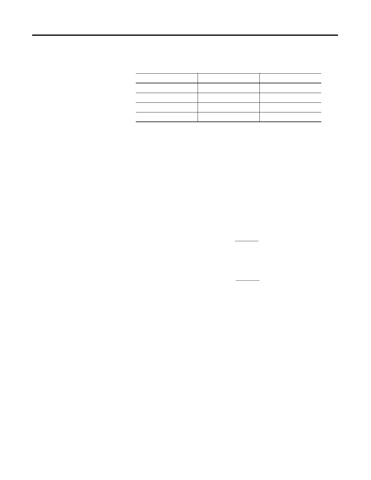
Table 19 - Current Imbalance Settings
Setting Prompt Setting Range Factory Default
CI TRIP LEVEL Off, 5…80% Off
CI TRIP DELAY 0…240 s 5
CI WARN LEVEL Off, 5…80% 10
CI WARN DELAY 0…240 s 10
UB% = 100 x
[(Im - Iav)]
Iav
UB% = 100 x
[(Im - Iav)]
FLA

 Loading...