20 Rockwell Automation Publication 825-UM004D-EN-P - November 2012
Chapter 2 Installation
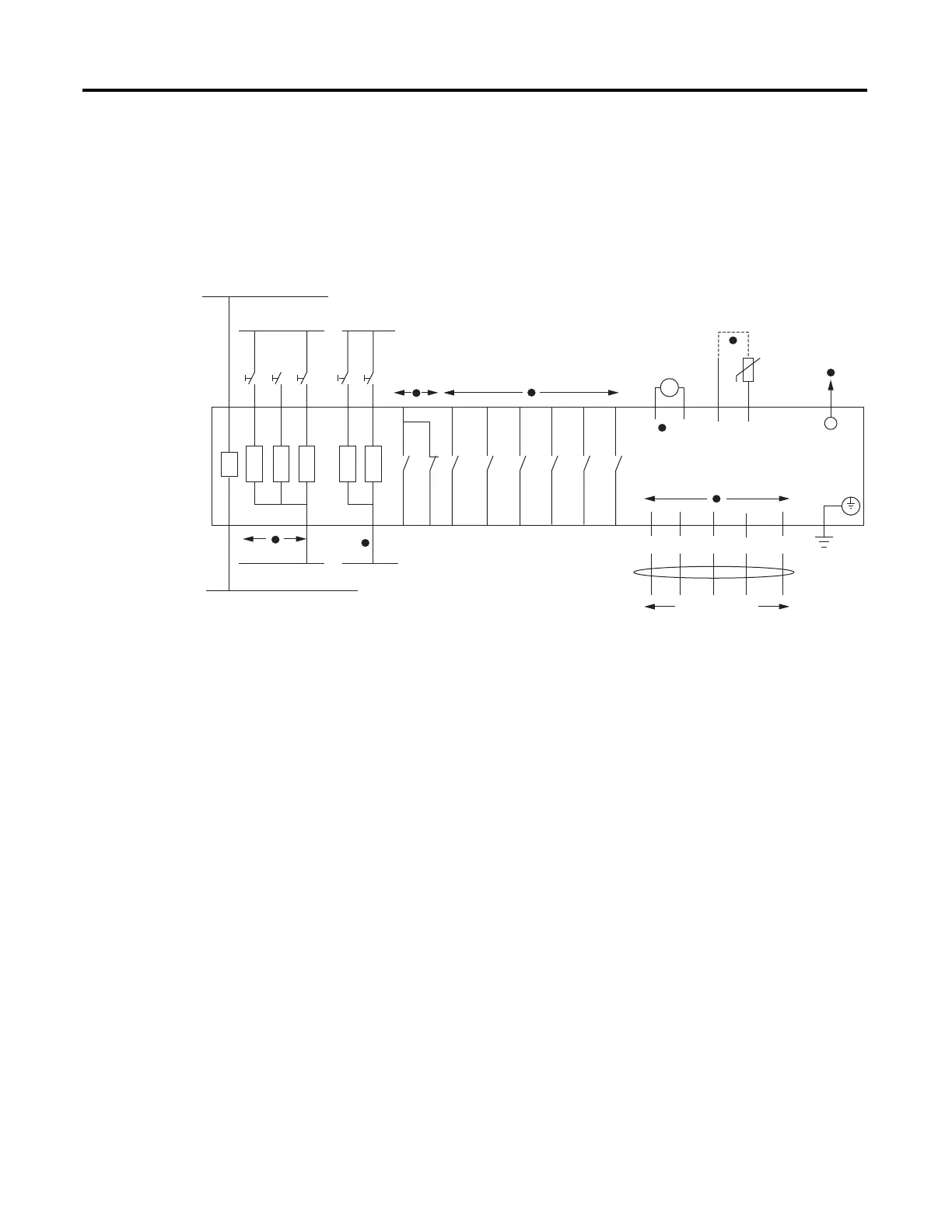
I/O Diagram
A more functional representation of the control (I/O) connections are shown
in Figure 5.
Figure 5 - Control I/O Connections in Powered-Down State
➊ See Table 44 for control function assignment to the input IN1 and IN2. Connect the appropriate external contacts (#1 and #2) to the
inputs.
➋ Inputs IN3, IN4, and IN5 are available when an optional I/O extension card is present. 825-PIOD inputs are rated 120V AC/DC. 825-PIOR
inputs are rated 24V AC/DC.
➌ See Table 42 for mapping protection elements to the Trip output. See Figure 7 and Figure 16 for typical control circuit connections.
➍ See Table 43 for mapping protection and/or control elements to the Aux outputs. Outputs Aux3 through Aux6 are available when an
optional I/O extension card is present.
➎ Analog Output is available when an optional I/O extension card is present.
➏ You can connect up to six thermistors (PTC) in series. See Table 2 for PTC cable requirements.
➐ Use up to 500 meter long Simplex 62.5/125 mm fiber-optic cable (ST/ST).
➑ Available when an optional DeviceNet Communications Protocol Card is present.
24V AC/+V DC24 or 120V AC/+V DC
24V AC/–V DC24 or 120V AC/–V DC
95
98 96
Trip
13
14
Aux1
Alarm
23
24
Aux2
33
34
Aux3
43
44
Aux4
53
Aux5
63
Aux6
RX
F/O Cable
to RTD Scanner
PS
A1
A2
110…240V AC, 24…48V DC
or 110…250 V DC
+ / H
– / N
825-P Relay
A
I +
Analog Out
T1
T2
PTC
I –
DeviceNet Cable
BK
V –
BU
CAN_L
SH
Drain
WH
CAN_H
RD
V +
Y1–
IN5
#1
IN4
#2
Y2–
IN3
#3
IN2
#4
IN1
Y26 Y24 Y22 Y14
Y12
#5
54
64
1
2
4
3
5
6
7
8

 Loading...